Solid electrolytic capacitor

a solid electrolytic capacitor and capacitor technology, applied in the direction of fixed capacitor details, casings/cabinets/drawers, electric apparatus casings/cabinets/drawers, etc., can solve the problems of high frequency including high harmonic components, and the esl of solid electrolytic capacitor x cannot be sufficiently lowered, so as to prevent the bending step from being broken and reduce the bending force

Inactive Publication Date: 2008-04-15
ROHM CO LTD
View PDF5 Cites 20 Cited by
  • Summary
  • Abstract
  • Description
  • Claims
  • Application Information

AI Technical Summary

Benefits of technology

[0011]Due to the above structure, the vertical portion extending in the first direction can be shortened, or be eliminated from the conductive path. Further, the conductive path can be bent by a minute angle. Thus, the conductive path can have a lowered inductance and thus have a small impedance at a high frequency range. Therefore, the structure is suitable to lower the ESL of the solid electrolytic capacitor. Further, the shortened vertical portion enables to make a thin solid electrolytic capacitor.
[0025]According to a preferable embodiment of the present invention, the ring is made of a resin. Due to this, the ring helps to reduce the bending force applied to the porous sintered body during the bending step. Further, the resin infiltrates into the porous sintered body from around the base of the metal rod. Thus, the relevant part of the porous sintered body is reinforced, and can be prevented from being broken in the bending step.

Problems solved by technology

Recently, noise at a high frequency including high harmonic component is generated by a device having a high clock frequency, such as a CPU.
Therefore, the solid electrolytic capacitor X cannot have a sufficiently lowered ESL.

Method used


Image

  • Solid electrolytic capacitor
  • Solid electrolytic capacitor
  • Solid electrolytic capacitor

Examples


Embodiment Construction

[0046]Preferred embodiments of the present invention will now be described below with reference to the accompanying drawings.

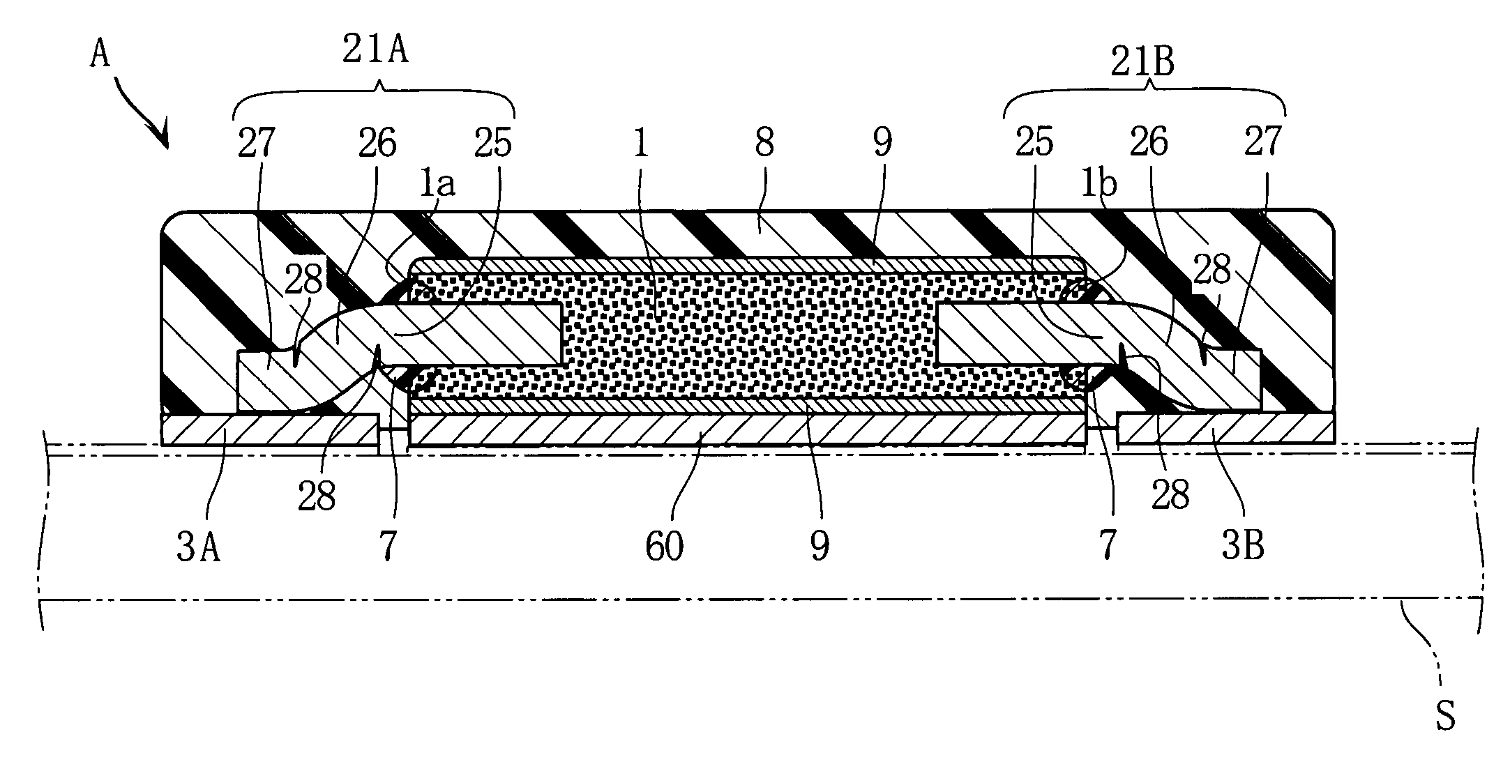
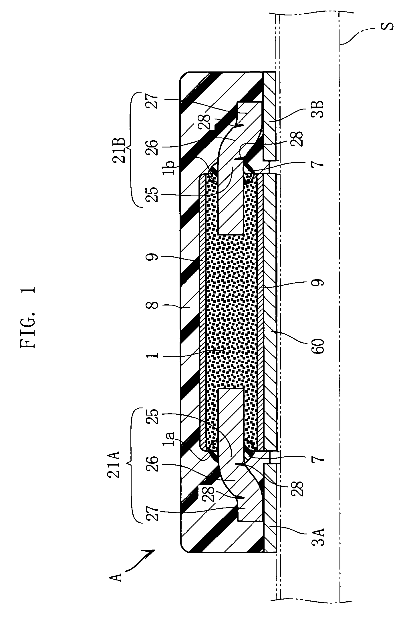
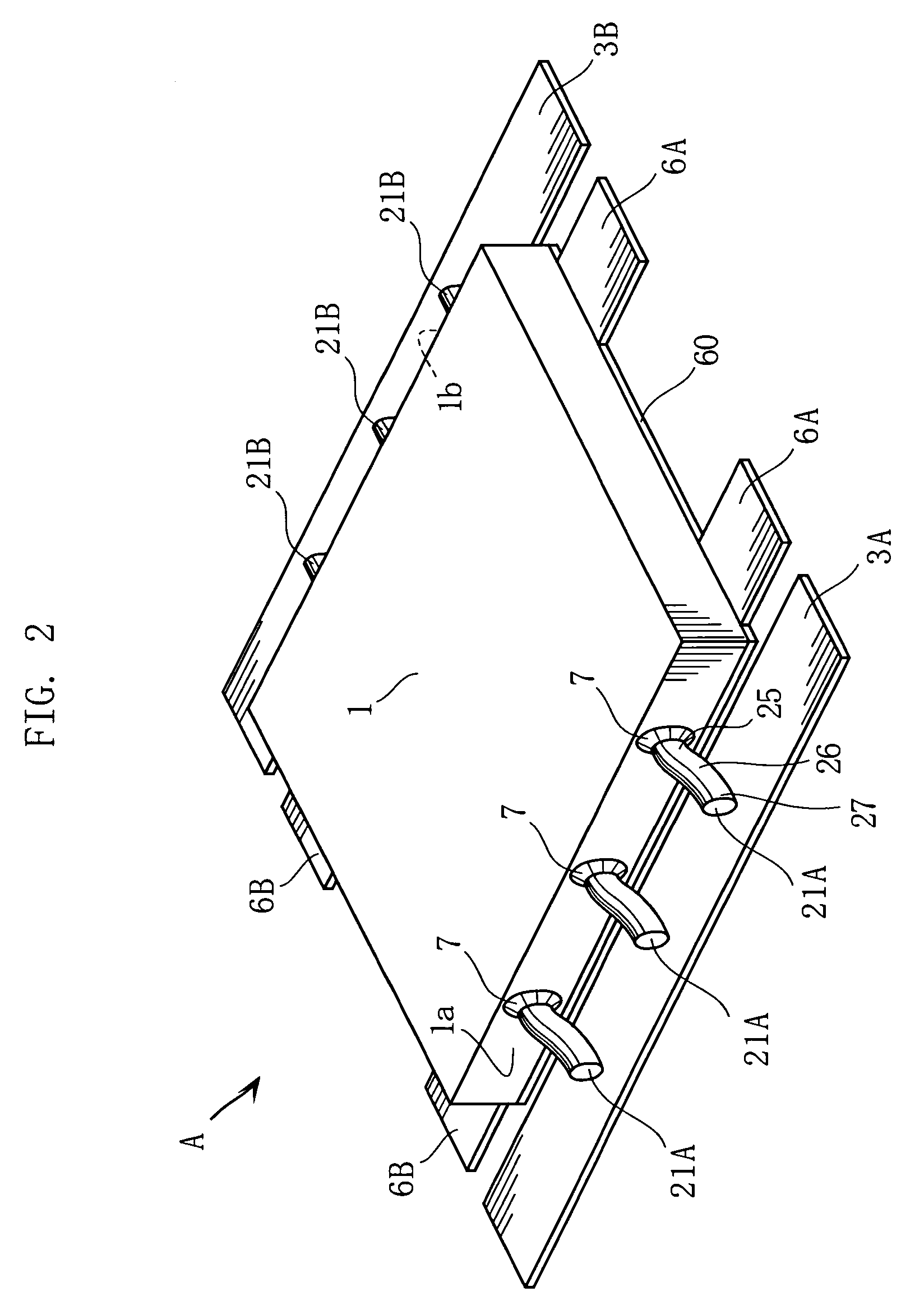
[0047]FIGS. 1 and 2 illustrate an example of a solid electrolytic capacitor according to the present invention. As shown in FIG. 1, the solid electrolytic capacitor A of the present embodiment includes a porous sintered body 1, anode wires 21A, 21B, external anode terminals 3A, 3B, external cathode terminals 6A, 6B, and a sealing resin 8. The sealing resin 8 is not shown in FIG. 2.

[0048]As shown in FIG. 2, the porous sintered body 1 is made of niobium having valve action, by compacting niobium powder to be a rectangular board and then sintering the board. In the sintered niobium powder making the porous sintered body 1, adjacent niobium particles form minute gaps. The surface of the above sintered powder is formed with a dielectric layer (not shown) made of niobium oxide, for example. Further, the surface of the dielectric layer is formed with a solid electrol...


PUM

PropertyMeasurementUnit
diameteraaaaaaaaaa
diameteraaaaaaaaaa
thicknessaaaaaaaaaa

Abstract

A solid electrolytic capacitor includes a porous sintered body made of valve metal, and an external anode terminal used for surface-mounting. The anode terminal is offset from the center of the sintered body, as viewed in the thickness direction or first direction of the sintered body. Further, the anode terminal is spaced away from the sintered body in a second direction which is perpendicular to the first direction. Between the sintered body and the anode terminal is formed a conductive path, which is inclined with respect to both the first and the second directions. The path comes closer to the anode terminal in the first direction as it goes farther away from the sintered body in the second direction.

Description

BACKGROUND OF THE INVENTION[0001]1. Field of the Invention[0002]The present invention relates to a solid electrolytic capacitor comprising a porous sintered body made of a valve metal, and also relates to a manufacturing method of making the same.[0003]2. Description of the Related Art[0004]An example of a solid electrolytic capacitor includes a capacitor utilized for canceling noise generated by a device such as CPU, or for stabilizing power supply for an electronic device. (Refer to JP-A-2003-163137, for example.) FIG. 19 illustrates an example of such a solid electrolytic capacitor. The illustrated solid electrolytic capacitor X includes a porous sintered body 90 made of a metal having valve action. The porous sintered body 90 is provided with an anode wire 91 partly protruding out thereof. The surface of the porous sintered body 90 is formed with a cathode conductive layer 92. Each of the anode wire 91 and the conductive layer 92 is connected to a respective one of conductive me...

Claims


Application Information

Patent Timeline
Patent Type & Authority Patents(United States)
IPC IPC(8): H01G4/228H01G9/00
CPCH01G2/065H01G9/042H01G9/012Y10T29/417
Inventor KURIYAMA, CHOJIRO
Owner ROHM CO LTD
Why Eureka
Try Eureka