
Redundancy arrangement for telecommunications switch

Active Publication Date: 2008-04-15
DIALOGIC INC
View PDF16 Cites 15 Cited by
  • Summary
  • Abstract
  • Description
  • Claims
  • Application Information

AI Technical Summary

Benefits of technology

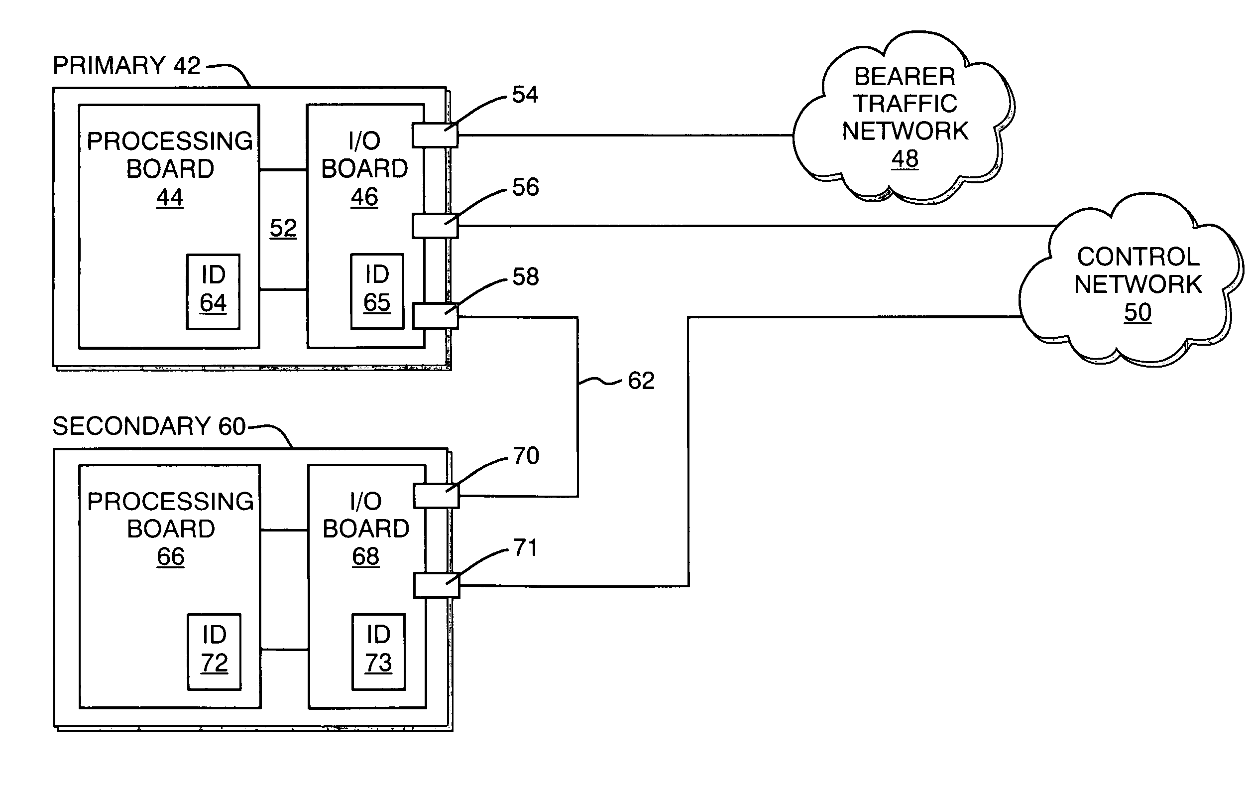
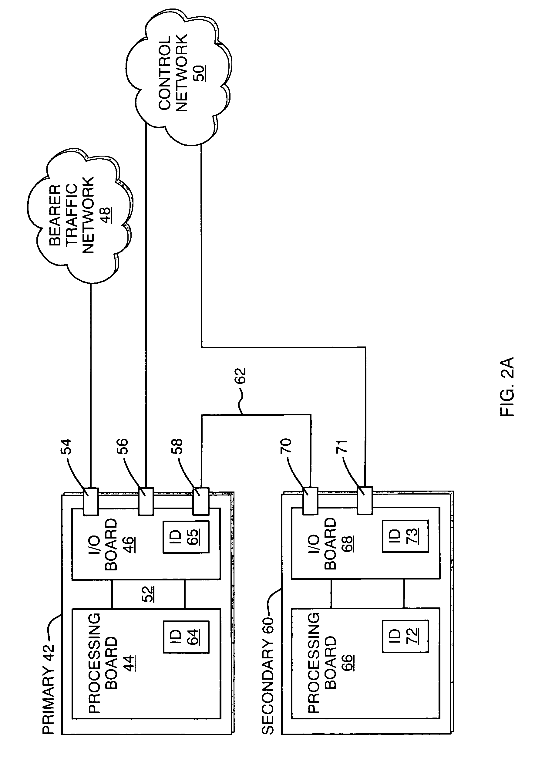
[0010]In accordance with the present invention, data communicated with sources external to the telecom switches is received or transmitted by the I / O board of the primary telecom switch. The secondary telecom switch, on the other hand, may only communicate to external sources through the redundancy connection to the I / O board of the primary telecom switch. In the event that the active board of the primary telecom switch should become unavailable, the passive I / O board of the primary telecom switch still remains available. Then, the secondary telecom switch assumes control of operations, and utilizes the redundancy connection with the I / O board of the primary telecom switch to communicate with the external sources. This process effectively eliminates the need to reconfigure the many connections to the telecom switches during such a situation, and minimizes any noticeable downtime. Also, these operations are completed without the need for direction from an external device, such as a host computer to message the available telecom switch to assume mastership.

Problems solved by technology

Usually, this level of redundancy is provided by the Internet carriers, and is outside the control of the telecom companies operating their own hardware applications, such as a converged services platform (CSP).
This procedure could result in network downtime where live calls are lost, and could create the possibility of having the many connections incorrectly arranged, causing further downtime.
While this solution maintains an active system should one unit fail, replacing the failed unit still requires physically removing all the connections from the failed unit for replacement.

Method used


Image

  • Redundancy arrangement for telecommunications switch
  • Redundancy arrangement for telecommunications switch
  • Redundancy arrangement for telecommunications switch

Examples


Embodiment Construction

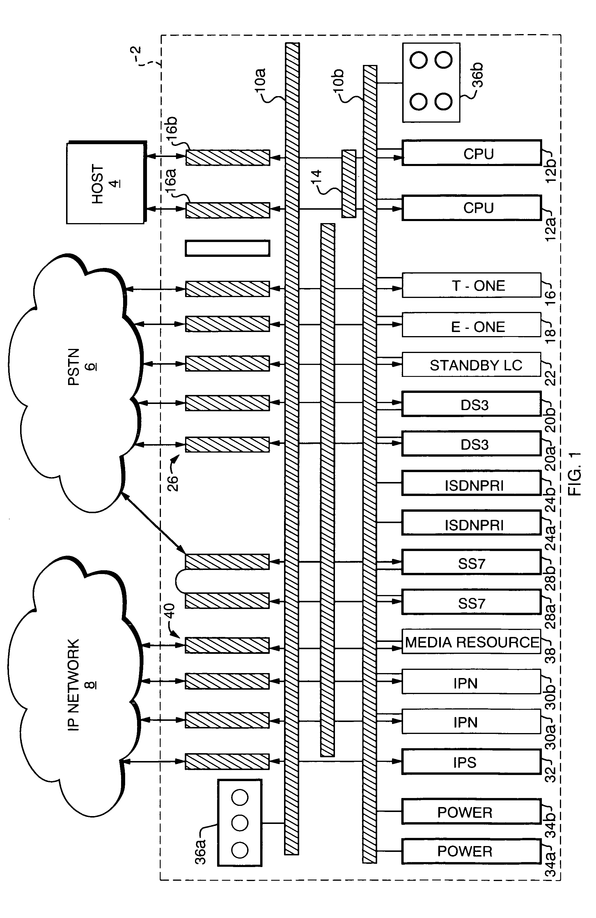
[0021]The invention described herein is readily adaptable for use with a variety of telecommunications switching systems and the scope of the invention is not limited to any particular architecture, or type of switching system. However, for purposes of illustration, one example of a telecommunications switching system with which the present invention may be employed is illustrated in FIG. 1. FIG. 1 shows a converged services platform (CSP) 2 which is controlled by an application program (not shown) running on a host computer 4. Hardware and software which may be used to implement a converged services platform of the type shown are available from Excel Switching Corporation of Hyannis, Mass. With the inclusion of appropriate cards discussed below, platform 2 is capable of interfacing with both the PSTN 6 and an IP network 8.

[0022]As shown, platform 2 includes redundant switching buses 10a and 10b. Redundant CPU cards 12a, 12b are connected to buses 10a, 10b, an HDLC bus 14, and to ho...


PUM


Abstract

A system and method are disclosed for providing redundancy for telecommunication switches. A primary telecom switch has an active processing board and a passive I / O board for communicating with external sources, such as a control network and bearer traffic network. A redundant secondary telecom switch has an active processing board and a passive I / O board for communicating with a control network, and is connected to the I / O board of the primary switch through a redundancy connection for communicating with the bearer traffic network. According to the invention, the secondary telecom switch assumes the role of the primary telecom switch in the event that the primary processing board becomes unavailable. The secondary telecom switch then communicates with the bearer traffic network as the master switch through the redundancy connection and the I / O board of the primary switch, thus avoiding the necessity for reconnections and reconfiguration.

Description

BACKGROUND OF THE INVENTION[0001]1. Field of the Invention[0002]The present inventions relates generally to the field of telecommunications and, more specifically, to a system and method for providing redundancy in a telecommunications switch.[0003]2. Background Information[0004]A continuing trend of convergence between the circuit-switched public switched telephone network (PSTN) and packet-switched networks, such as Internet Protocol (IP) networks, has created demand for systems capable of interfacing with both types of networks while supporting a large number of diverse applications. Such applications include toll-free calling, wireless / wireline prepaid calling, directory assistance, voicemail, call centers, conferencing and many others. In order to support such diverse applications, it is generally necessary to provide a capability for performing DTMF tone generation / detection, voice recorded announcements and similar communications services. Such basic capability, conventionall...

Claims


Application Information

Patent Timeline
IPC IPC(8): H04L12/26
CPCH04L69/40
Inventor DECESARE, JOHN R.ALLEN, JAMES F.AMARAL, OCTAVIO P.
Owner DIALOGIC INC
Learn More