Long range artillery shell

a technology of artillery shells and shells, applied in the field of long-range artillery shells, can solve the problems of catastrophic shell failure, general relativity high-cost munitions, and failure of the motor to ignite, and achieve the effect of reducing the drag on the bas

Inactive Publication Date: 2008-04-22
QINETIQ LTD
View PDF8 Cites 4 Cited by
  • Summary
  • Abstract
  • Description
  • Claims
  • Application Information

AI Technical Summary

Benefits of technology

[0012]According to the present invention there is provided a long range artillery shell comprising a payload, a rocket motor and a rocket motor delay mechanism for delaying ignition of the rocket motor for a predetermined time after launch of the shell wherein the rocket motor comprises a combustion chamber, a plenum chamber located at one end of the combustion chamber, a rocket nozzle for venting the plenum chamber, a solid rocket propellant being arranged in an end-burn configuration and housed within the combustion chamber and a propellant support located between the propellant and the plenum chamber wherein the propellant support is adapted to prevent substantial movement of the propellant during launch, to prevent entry of unburnt propellant into the plenum chamber and to permit in use the substantially unhindered transfer of propellant combustion products to the plenum chamber.
[0013]By providing a solid propellant without a central cavity the level of the axial acceleration load which the propellant can withstand is increased over that of a propellant formed from the same material but with a central cavity. During launch the propellant is supported and prevented from substantial movement by the propellant support, overcoming the tendency for the propellant to move backwards and close up the plenum chamber which would produce incorrect ignition. Problems with inconsistent burning are removed as the propellant support also serves to prevent substantial amounts of unburnt propellant from entering the plenum chamber to adversely effect the burning characteristics of the rocket motor. Moreover, by providing only one support for the propellant the volume of combustion chamber available for propellant is maximised.
[0018]In a preferred embodiment the propellant support comprises a perforated plate and cooperable load transfer means which is adapted to transfer a proportion of the axial acceleration loads experienced during launch to the walls of the plenum chamber. This reduces the loads which the perforated plate must be capable of withstanding thereby allowing a relative reduction in the thickness of the plate. This has the advantage that more propellant may be accommodated within the combustion chamber.
[0021]Most usefully the long range artillery shell may also include a base bleed system. Such systems are common in the art and are effective at reducing base drag when the shell is moving at high velocity through the relatively dense air found during the initial stages of flight.

Problems solved by technology

Missiles, however, are generally relatively high cost munitions, a large part of the volume of which is rocket motor, and are launched by ignition of the rocket motor.
These high axial loads during launch of an artillery shell would cause movement and deformation of the propellant in a rocket motor which could result in failure of the motor to ignite after launch or catastrophic failure of the shell.
However one problem associated with this type of rocket motor is that the perforated grain propellant may deform when subjected to the high axial acceleration loads experienced during launch.
In so deforming the solid propellant may develop a crack or may deform plastically to close up the central cavity.
In either case, misfunction of the motor and sometimes catastrophic failure of the shell can result.
However, this solution introduces the additional problem that the volume of the combustion chamber available for propellant is decreased by these supports.
This results in either a reduced payload or a reduced range if the mass and external dimensions of a conventional shell are to be retained.

Method used


Image

  • Long range artillery shell
  • Long range artillery shell
  • Long range artillery shell

Examples


Embodiment Construction

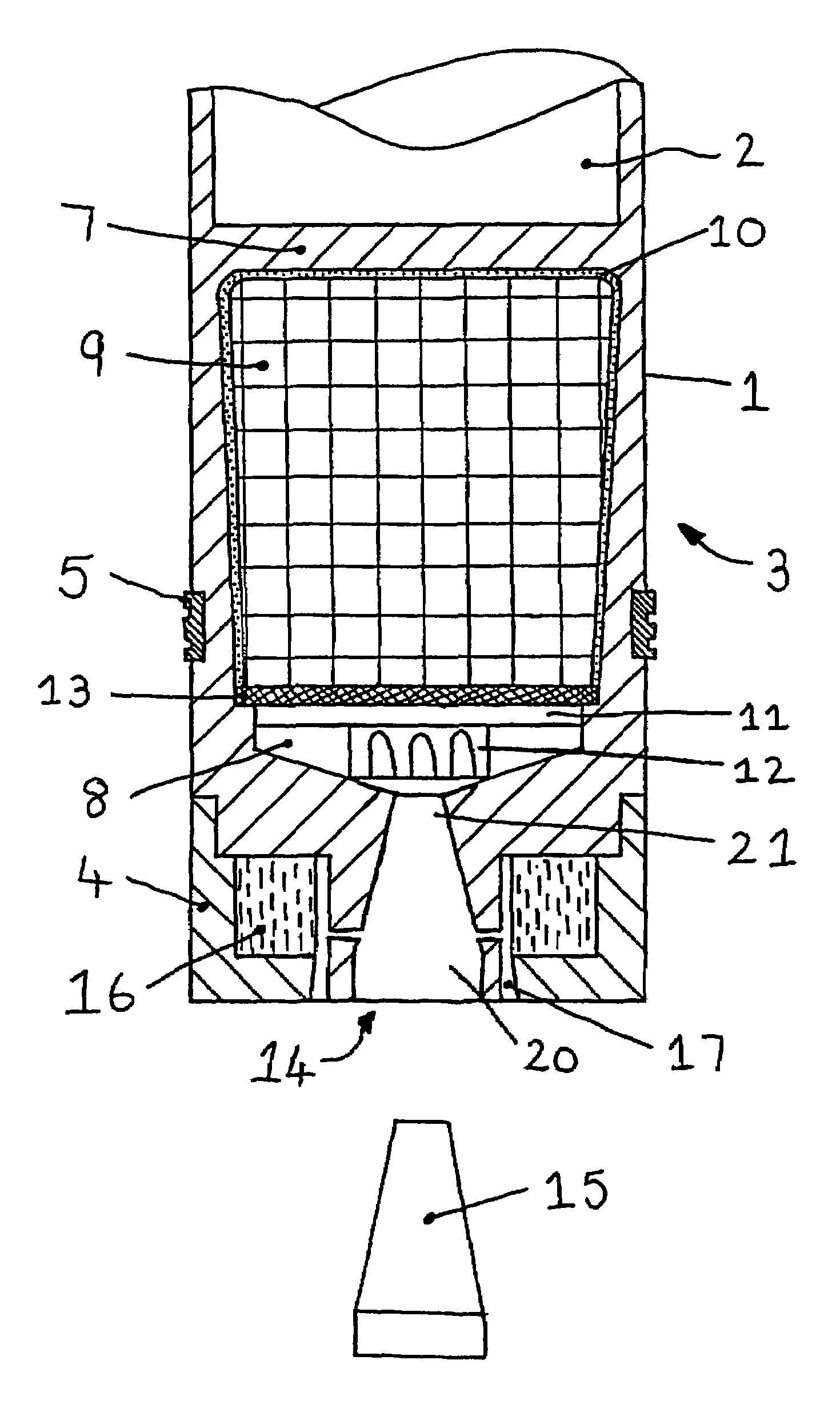
[0026]Referring now to FIG. 1 a 155 mm artillery shell is shown which generally comprises a payload volume 2, a rocket motor 3 and base bleed unit 4 and a driving band 5.

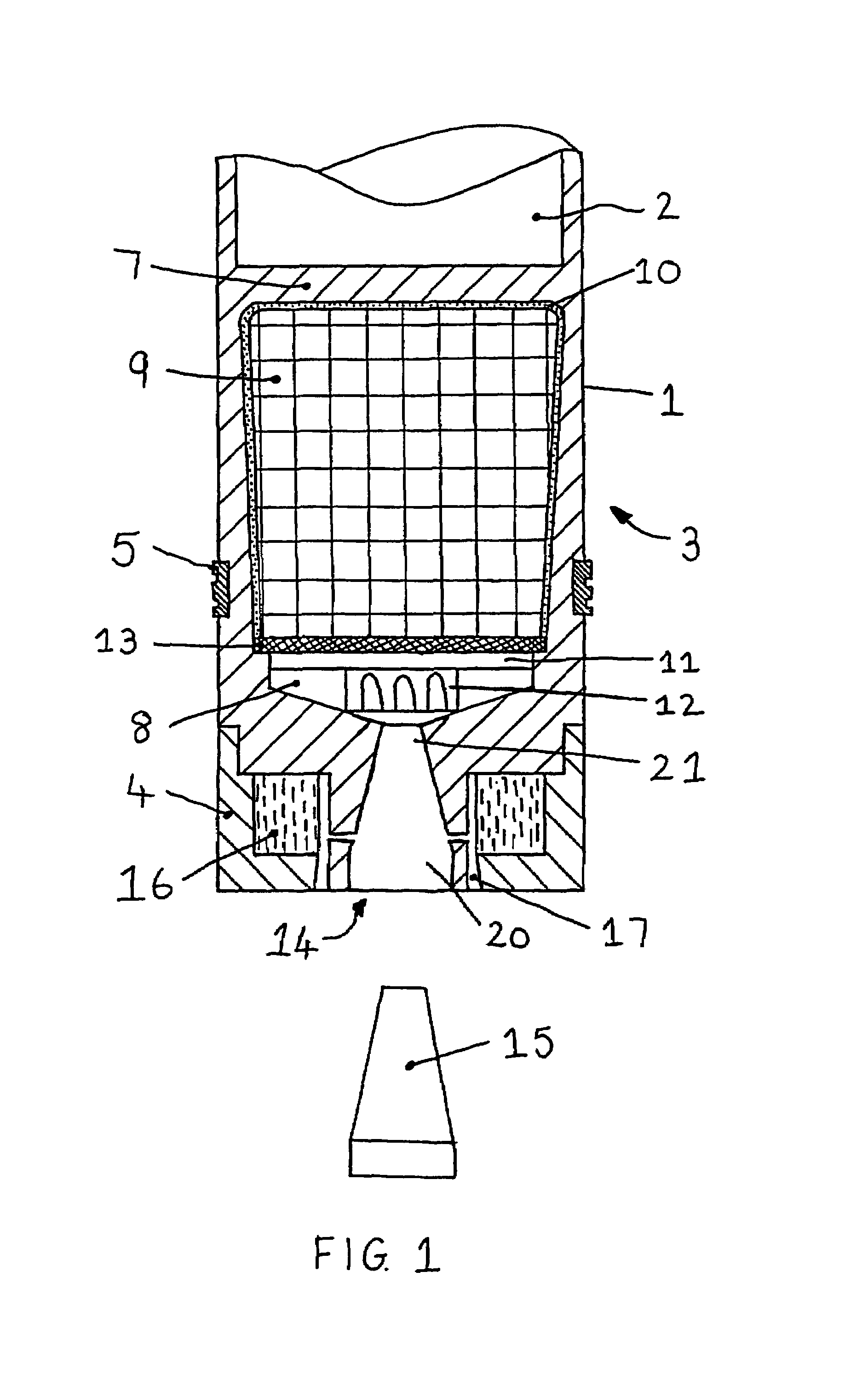
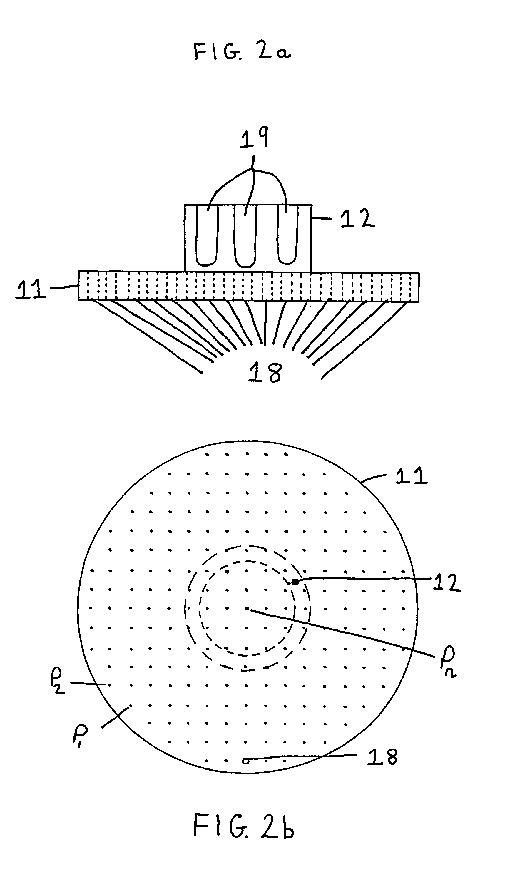
[0027]The payload volume 2 and the combustion chamber (shown containing propellant 9, burn inhibitor 10 and igniter material 13) are separated by a bulkhead 7 with the combustion chamber being defined by the wall of the shell 1. The volume of the combustion chamber is reduced towards the end distal from the bulkhead 7 to form a plenum chamber 8. A single grain of rocket propellant 9, having been previously cast in a burn inhibitor 10, is configured to fill the majority of the volume of the combustion chamber. The propellant 9 is prevented from entering the plenum chamber 8 by a thin perforated plate 11 and associated load ring 1-2. A layer of igniter material 13 for igniting the exposed end face of the propellant 9 is provided between the plate 11 and the propellant 9. The plenum chamber 8 can be vented by the rocke...


PUM


Abstract

A long range artillery shell having a rocket motor which comprises a combustion chamber (shown filled with solid propellant 9, burn inhibitor 10, igniter material 13 and propellant support 11,12) which has at one end a plenum chamber 8 and a rocket nozzle 14 for venting the plenum chamber 8. The propellant 9 is arranged in an end-burn configuration and housed within the combustion chamber and the propellant support 11,12 is located between the propellant 9 and the plenum chamber 8 and is capable of preventing entry of unburnt propellant into the plenum chamber 8 while permitting, in use, the substantially unhindered transfer of propellant combustion products to the plenum chamber 8.

Description

BACKGROUND OF THE INVENTION[0001]1. Field of the Invention[0002]This invention relates to a long range artillery shell having a rocket motor.[0003]2. Discussion of Prior Art[0004]There is a constant military requirement to extend the range of artillery shells with minimum effect on the payload and the delivery system. In practice this requires the general physical shape of the conventional shell to be maintained since if the long range artillery shell conforms closely to the mass and external dimensions of the conventional shell it may then be delivered using existing ordnance without exceeding the maximum acceptable breech pressure.[0005]One method to increase the range of a shell is to provide that shell with a rocket motor which is ignited after the round has left the barrel to provide additional impulse to the shell, thereby increasing its range.[0006]Rocket motors are well known for missile systems. For example, UK patent GB676368 discloses a missile with a rocket motor having ...

Claims


Application Information

Patent Timeline
Patent Type & Authority Patents(United States)
IPC IPC(8): F02K9/36
CPCF02K9/36F02K9/425F02K9/44F05D2250/82
Inventor GADIOT, GUILLAUME M. H. J. L.
Owner QINETIQ LTD
Why Eureka
Try Eureka