Apparatus and method for hydroshearing and hydrotrimming for hydroforming die

a technology of apparatus and hydroshearing, which is applied in the field of apparatus and methods for hydroshearing and hydrotrimming of hydroforming dies, can solve the problems of increasing manufacturing cost and time, increasing costs, and hydroforming die down time, and achieves the effects of less expensive, less time, and saving fluid forming pressur

Active Publication Date: 2008-04-22
GM GLOBAL TECH OPERATIONS LLC
View PDF9 Cites 2 Cited by
  • Summary
  • Abstract
  • Description
  • Claims
  • Application Information

AI Technical Summary

Benefits of technology

[0008]One advantage of the present invention is that a new apparatus and method of hydrotrimming and hydroshearing is provided for a hydroforming die that has the ability to end trim tubular members. Another advantage of the present invention is that the apparatus and method eliminates a post-forming secondary operation of mechanically shearing or laser cutting the end(s) of tubular members, which is less expensive. Yet another advantage of the present invention is that the apparatus and method does not add additional time during hydroforming since the end is cut from the tubular member in the die during the overall forming of the tubular member. Still another advantage of the present invention is that the apparatus and method seal the tubular member, thereby conserving fluid forming pressure and synchronization of a multitude of other punches and die operations is not required. A further advantage of the present invention is that the apparatus and method allows the ends of the tubular member to be trimmed at anytime during the forming cycle as pressure is not lost during the end trimming of the tubular member. Yet a further advantage of the present invention is that the apparatus and method has wear parts that are disposable and easy to replace, providing a significant improvement in the hydroforming process. Still a further advantage of the present invention is that the apparatus and method requires fewer machines and reduces overall downtime since the forming fluid does most of the work of trimming.
[0009]Other features and advantages of the present invention will be readily appreciated, as the same becomes better understood, after reading the subsequent description taken in conjunction with the accompanying drawings.

Problems solved by technology

Both of these added requirements increase the manufacturing cost and time.
Unless the forming and the shearing operations are equal in length of time, more expense is incurred.
If the shearing operation is slower, the tubular members must be inventoried or the hydroforming die will have down time.
If the forming process is slower, the shearing apparatus will have down time.

Method used


Image

  • Apparatus and method for hydroshearing and hydrotrimming for hydroforming die
  • Apparatus and method for hydroshearing and hydrotrimming for hydroforming die
  • Apparatus and method for hydroshearing and hydrotrimming for hydroforming die

Examples


Embodiment Construction

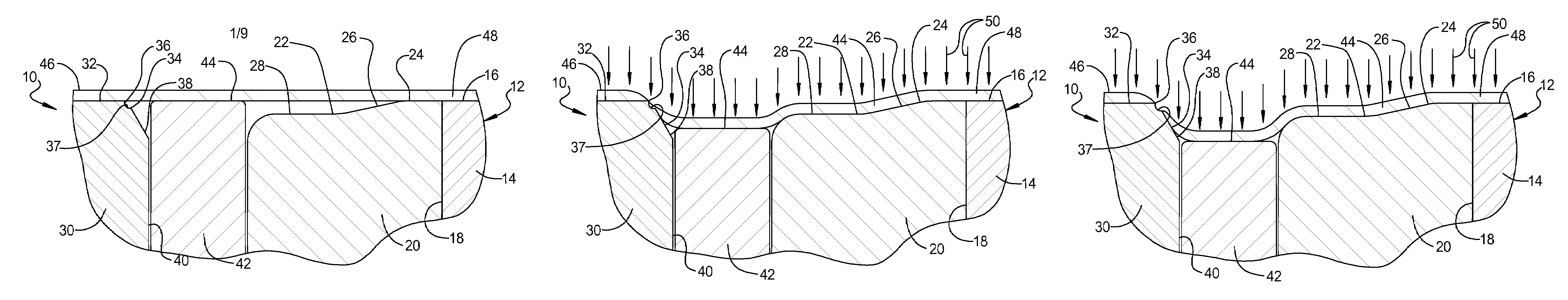
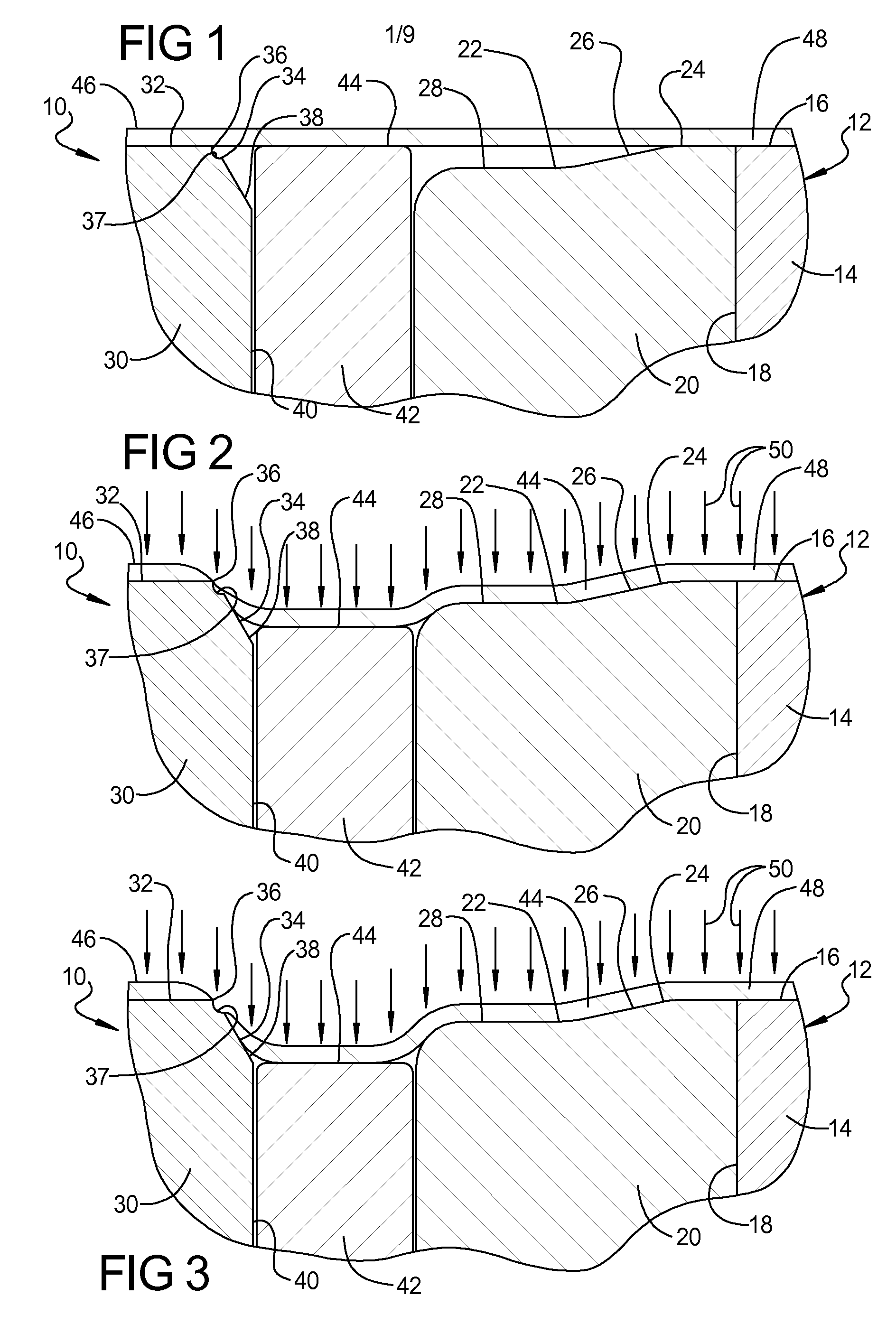
[0024]Referring to the drawings and in particular FIG. 1, one embodiment of an apparatus 10, according to the present invention, is generally shown for a hydroforming die, partly shown and generally indicated at 12. The hydroforming die 12 is a die set comprised of a lower die half and an upper die half. In the embodiment illustrated, only one die half 14 is shown. The die half 14 also includes a tubular forming cavity portion 16. The die half 14 includes a cavity 18 extending axially from the tubular forming cavity portion 16. An example of such a hydroforming die 12 is disclosed in U.S. Pat. No. 5,941,112 to Ghiran et al., the disclosure of which is hereby incorporated by reference. It should be appreciated that hydroforming dies are conventional and known in the art.

[0025]The apparatus 10 also includes at least one disposable insert 20 disposed within the die half 14. The disposable insert 20 is disposed within the cavity 18 and does not move relative to the die half 14. The disp...


PUM

PropertyMeasurementUnit
pressureaaaaaaaaaa
lengthaaaaaaaaaa
timeaaaaaaaaaa

Abstract

An apparatus and method for hydroshearing and hydrotrimming for a hydroforming die includes a cutting insert fixed relative to the hydroforming die. The apparatus and method also includes a disposable insert fixed relative to the hydroforming die. The apparatus and method further includes a plunger movable relative to the hydroforming die to allow fluid within a tubular member to force a wall portion of the tubular member outward against the plunger and be sheared in the hydroforming die to trim the tubular member.

Description

TECHNICAL FIELD[0001]The present invention relates generally to hydroforming and, more specifically, to an apparatus and method for hydroshearing and hydrotrimming for a hydroforming die.BACKGROUND OF THE INVENTION[0002]It is known to form a cross-sectional profile of a tubular member by a hydroforming process in which a fluid filled tubular member is placed within a cavity of a die and then the die is closed so that the tubular member is pinched within the die. Fluid pressure is then increased inside the tubular member to expand the tubular member outwardly against the cavity of the die to provide a tubular member having a die formed cross-sectional profile.[0003]After preliminary shaping in the hydroforming die, the tubular member is removed from the die for further machining, processing, or fabricating. The tubular member is trimmed to have a desired length in a separate shearing operation. The length is established by laser cutting, plasma cutting, or mechanical shearing outside...

Claims


Application Information

Patent Timeline
Patent Type & Authority Patents(United States)
IPC IPC(8): B21D26/02B21D28/18
CPCB21D26/035B21D26/047B21D28/18
Inventor GHIRAN, MIKE M.LARSEN, PAUL D.JENSEN, DAVID R.HARMON, GERRY A.SHAH, SANJAY M.KENT, TERRY A.
Owner GM GLOBAL TECH OPERATIONS LLC
Why Eureka
Try Eureka