Gravity gradiometer

a gravity gradient and gravity gradiometer technology, applied in the field of gravity gradients, can solve the problems of limited performance of airborne gravity gradiometers, weight, size, complexity of liquid helium cryostats, etc., and achieve the effect of improving characteristics

Active Publication Date: 2008-04-22
GEDEX
View PDF7 Cites 97 Cited by
  • Summary
  • Abstract
  • Description
  • Claims
  • Application Information

AI Technical Summary

Benefits of technology

[0010]Accordingly, it is an object of the present invention to provide improved OQR-type gravity gradiometers which have improved characteristics, and which in some embodiments can be operated without the need for cryogenic cooling.

Problems solved by technology

Moreover, when the gravity gradiometer is mounted in a moving vehicle, the signals due to these gravity gradient changes are very small in comparison to the undesirable responses of the instrument produced by accelerations of the vehicle on which the instrument is mounted.
The performance of present commercially operating airborne gravity gradiometers is currently limited to an error level of about 5 Eotvos (1 Eo=gradient of 10−9 meters per second squared per meter, approximately 10−10 g per meter) at a signal averaging time of 6 seconds.
The necessity for liquid helium supply in the field, and the weight, size, and complexities associated with the liquid helium cryostat are undesirable features.
These webs are fragile, especially at higher temperatures similar to room temperature, and are prone to breaking.
In addition, it is difficult to achieve requisite dimensional tolerances when manufacturing that type of web flexure.

Method used


Image

  • Gravity gradiometer
  • Gravity gradiometer
  • Gravity gradiometer

Examples


first embodiment

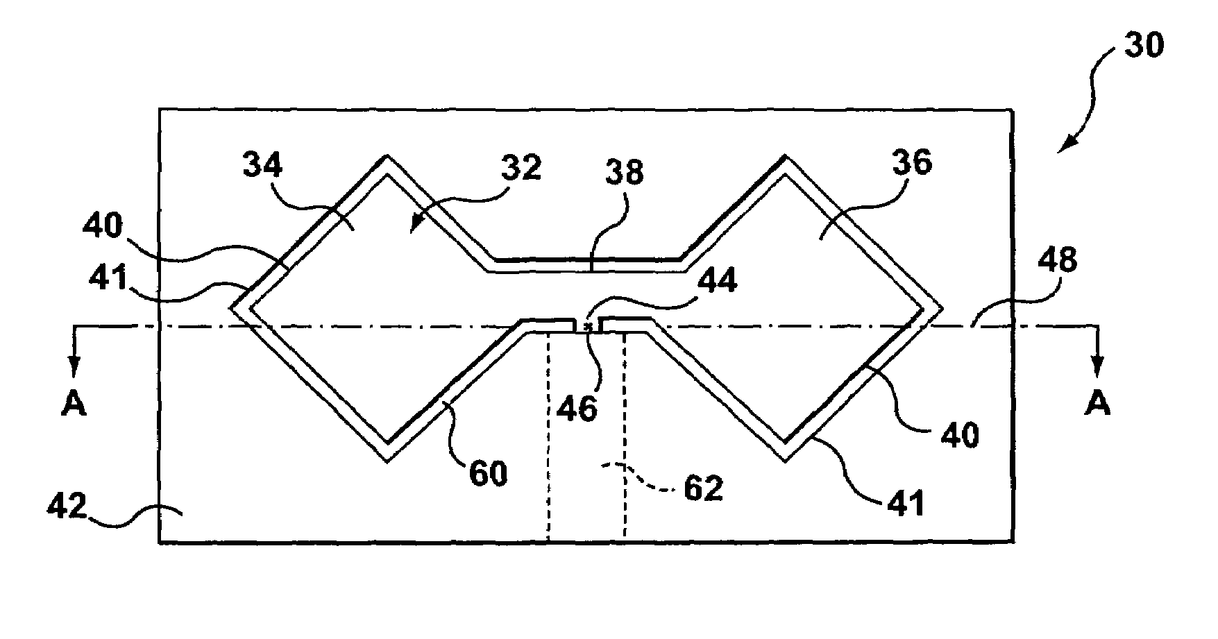
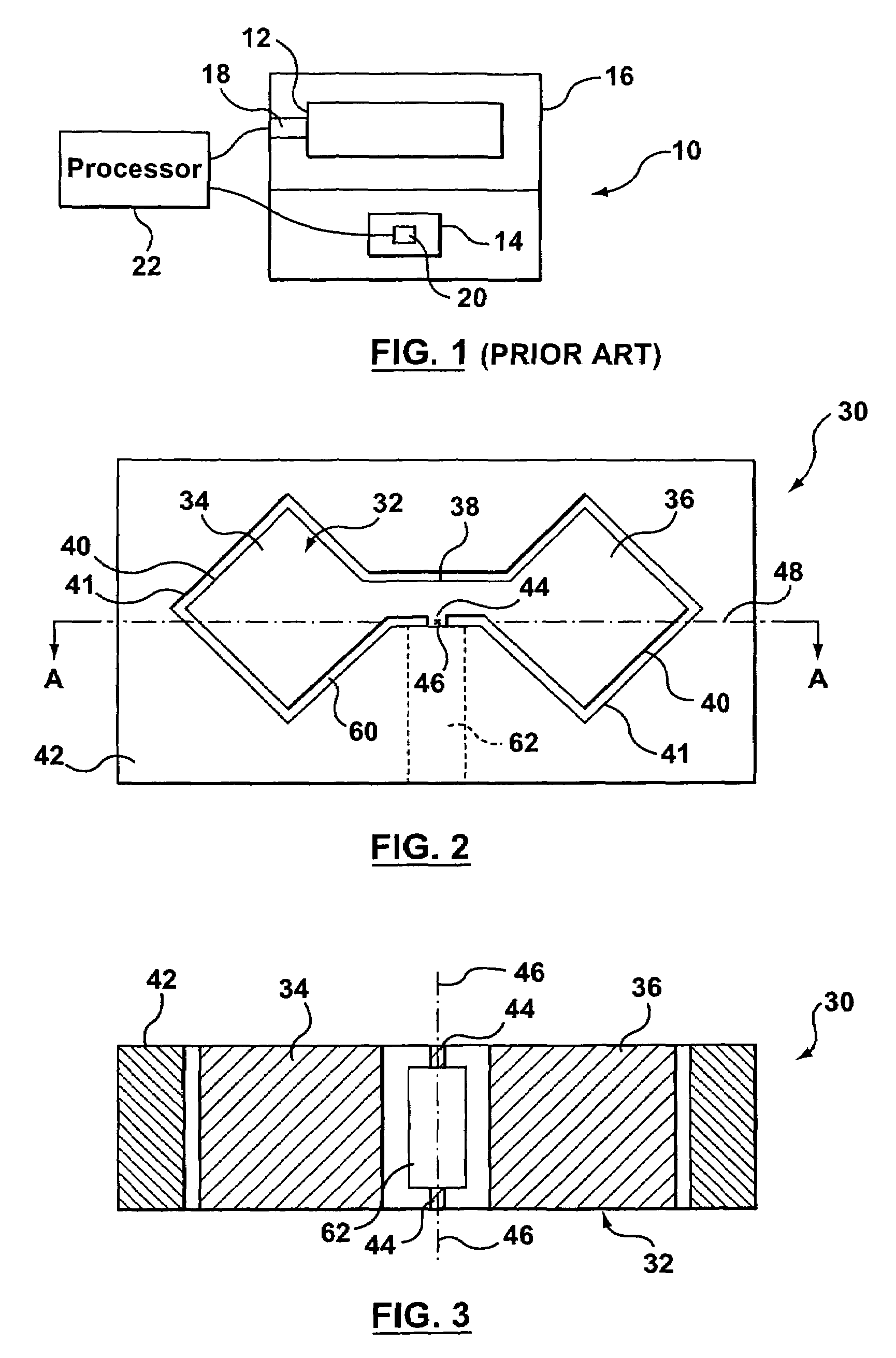
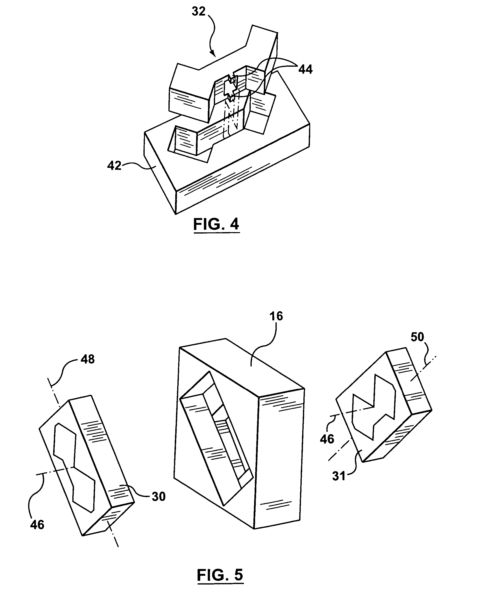
[0025]Reference is next made to FIGS. 2 to 4, which show a quadrupole responder 30 of an OQR-type gravity gradiometer according to the invention. As discussed, a gravity gradiometer would normally include two quadrupole responders 30, 31 (FIG. 5).

[0026]As shown in FIGS. 2 to 4, the quadrupole responder 30 includes a bow tie shaped mass quadrupole or balance beam 32, having two enlarged end portions 34, 36 joined by a center portion or bridge 38. The bow tie shape shown is convenient to increase the quadrupole moment of the mass quadrupole or balance beam 32 (thus increasing its response to gravity gradients) and to provide faces 41 on which to mount sensors to detect motion of the quadrupole responder (as will be described).

[0027]The mass quadrupole 32 is located in a housing 42 and is supported on the housing by a torsional spring comprising two or more flexure posts 44 (a pair of such posts is shown in FIGS. 3 and 4). Line 46 running through the center of flexure of each of the fl...

second embodiment

[0107]For this second embodiment of the invention involving the use of glassy metal materials for the flexures of quadrupole responders, there are several well-known manufacturing processes that are available for making such flexures and quadrupole responder structures using glassy metals. In one of these techniques (direct casting), a mould is made which is a matrix for the final part (that is, whose internal cavity has the desired shape of the final part). This mould is placed in a quench medium (e.g. anti-freeze containing dry ice). The constituent elements of the selected glassy metal are placed in a receptacle, such as a crucible or a sealed quartz chamber, and heated to a temperature above the liquidus of the glassy metal. The molten glassy metal is then injected or allowed to flow from the receptacle into the mould; the quench medium surrounding the mould causes sufficiently rapid cooling to produce a glassy metal structure of the desired shape in a bulk form.

[0108]However in...


PUM


Abstract

A gravity gradiometer having quadrupole responders in which a mass quadrupole is supported by a torsional spring forming a flexure allowing rotation of the mass quadrupole about its center of mass. The flexure can be a pair of spaced apart posts. The flexure can be made from glassy metal having at room temperature a high elastic limit, high stiffness, high strength and low internal damping. The flexure can alternatively be a web made of glassy metal.

Description

PRIOR APPLICATION[0001]This application claims the benefit of U.S. Provisional Application Ser. No. 60 / 703,502 filed Jul. 29, 2005 entitled “GRAVITY GRADIOMETER”.FIELD OF THE INVENTION[0002]This invention relates to a gravity gradiometer.BACKGROUND OF THE INVENTION[0003]Gravity gradiometers have existed for many years and are used to measure variations in the gradient of the earth's gravitational field. Gravity gradiometers may be used in exploration for minerals and hydrocarbons, since deposits of these things in the earth, and variations in the underground structure containing the deposits, produce variations in gravity and in the gravitational gradients which if interpreted correctly can lead to valuable discoveries. The ability to operate a gravity gradiometer in a moving vehicle is desirable, since doing so can greatly decrease the amount of time needed to carry out a survey of a given site.[0004]The variations in the gravity gradients which must be measured are extremely small...

Claims


Application Information

Patent Timeline
Patent Type & Authority Patents(United States)
IPC IPC(8): G01V7/00G01M1/12
CPCG01V7/10
Inventor FRENCH, JOHN BARRYCARROLL, KIERAN A.THORPE, STEVEN J.
Owner GEDEX
Why Eureka
Try Eureka