Pressure sensor device including a diaphragm and a stopper member having a curved surface facing the diaphragm

a technology of pressure sensor and diaphragm, which is applied in the direction of pressure difference measurement between multiple valves, variable capacitors, instruments, etc., can solve the problems of b>2/b>, and achieve the effect of preventing a diaphragm breakdown, simple structure and increasing withstand pressur

Active Publication Date: 2008-04-22
YAMATAKE HONEYWELL CO LTD
View PDF12 Cites 47 Cited by
  • Summary
  • Abstract
  • Description
  • Claims
  • Application Information

AI Technical Summary

Benefits of technology

[0010]The present invention has been made in light of the above circumstances, and an object thereof is to provide a pressure sensor device capable of sufficiently increasing operating pressure for protection against maximum pressure with respect to a sensor chip and having a simple structure that can be downsized.
[0014]With the pressure sensor device having a structure in which the stopper member including the concave portion forming the above-described curved surface is disposed to face the diaphragm, the entire diaphragm that is displaced upon receiving maximum pressure is brought into uniform contact to the concave portion of the stopper member. Therefore, all the pressure applied to the diaphragm is evenly received by the curved surface of the concave portion of the stopper member. As a result, local stress concentration does not occur in the diaphragm, and the maximum pressure applied to the diaphragm is evenly dispersed through the entire diaphragm, which makes it possible to effectively prevent a breakdown of the diaphragm. It is also possible to sufficiently increase operating pressure for protection against maximum pressure p as the pressure sensor device.
[0015]In case that a pressure transmitting medium such as silicone oil is led to the diaphragm, it is preferable that a leading hole for the pressure-transmitting medium be formed in a top portion of the concave portion forming the curved surface of the stopper member. If the pressure leading hole is formed in the top portion of the concave portion in the stopper member as mentioned, the presence of the pressure leading hole that opens in the curved surface of the concave portion can be practically disregarded. Therefore, it is possible to easily design the curved surface of the concave portion in view of only a displacement characteristic of the diaphragm, which is caused by pressure application.
[0018]According to the present invention, since there are provided the stopper members including the concave curved surfaces parallel to the surfaces formed by displacement of the diaphragm, it is possible to effectively prevent a breakdown of the diaphragm attributable to maximum pressure and to sufficiently increase the withstand pressure thereof in spite of the simple structure. Consequently, the present invention offers practically significant advantages including the advantage that there is no need for a meter body with a center diaphragm, which enables substantial downsizing.

Problems solved by technology

Consequently, the necessity of the meter body 2 is a great issue in consideration of downsizing of the pressure sensor device.

Method used


Image

  • Pressure sensor device including a diaphragm and a stopper member having a curved surface facing the diaphragm
  • Pressure sensor device including a diaphragm and a stopper member having a curved surface facing the diaphragm
  • Pressure sensor device including a diaphragm and a stopper member having a curved surface facing the diaphragm

Examples


Embodiment Construction

[0034]A pressure sensor device according to an embodiment of the present invention will be described below with reference to the drawings.

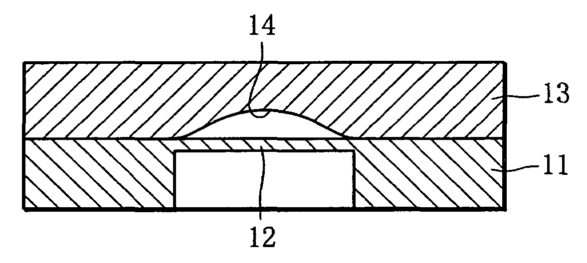
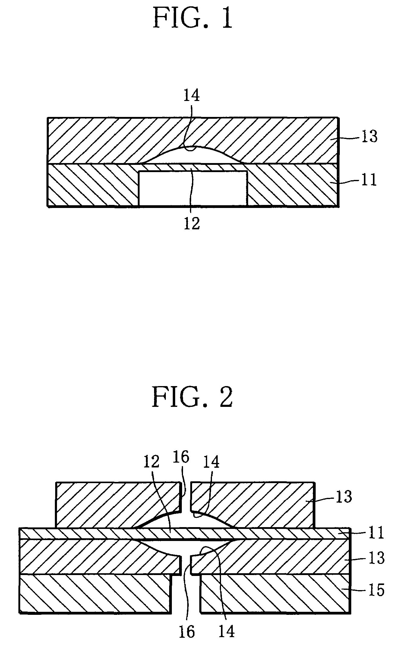
[0035]FIG. 1 is a sectional view of a substantial part, showing a basic structure of a pressure sensor device according to the present invention. Reference numeral 11 represents a base body in which a thin diaphragm 12 with a prescribed diameter is formed. The base body 11 is made of brittle material such as silicon (Si) and glass. Reference numeral 13 denotes a stopper member that includes a concave portion 14 facing the diaphragm 12 and is integrally joined to the base body 11. The concave portion 14 is formed as a curved surface parallel to a surface (displacement surface) formed by displacement of the diaphragm 12.

[0036]The curved surface of the concave portion 14 is a curved surface in which when the diaphragm 12 has a radius of r, a thickness of t, and a flexural rigidity of D, depth y at a distance x from the center of the diaphragm 12 in r...


PUM

PropertyMeasurementUnit
thicknessaaaaaaaaaa
thicknessaaaaaaaaaa
stress concentrationaaaaaaaaaa

Abstract

The pressure sensor device has a laminated diaphragm (12) in which a strain resistance gauge is formed in a surface and a stopper member (13) including a concave portion forming a curved surface parallel to a surface formed by displacement of the diaphragm, the concave portion being disposed to face the diaphragm. Specifically, the concave portion of the stopper member is formed into a curved surface in which depth y at a distance x from the center of the diaphragm is expressed by a quartic function [y=pr4(1−x2 / r2)2 / 64D] in relation to the operating pressure for protection against maximum pressure p when the diaphragm has a radius of r, a thickness of t, and a flexural rigidity of D.

Description

[0001]This application is a U.S. National Phase Application under 35 USC 371 of International Application PCT / JP2004 / 012001 filed Aug. 20, 2004.TECHNICAL FIELD[0002]The present invention relates to a pressure sensor device capable of sufficiently increasing operating pressure for protection against maximum pressure and having a simple structure that can be downsized.BACKGROUND ART[0003]A diaphragm-type pressure sensor device has a sensor chip in which, schematically, a strain resistance gauge is formed on a laminated diaphragm made of silicon, glass or the like. Based on a change of a resistance value of the strain resistance gauge formed in the diaphragm that is displaced by pressure, the pressure sensor device detects the pressure applied to the diaphragm.[0004]For example, a pressure sensor device of this type is configured by installing a sensor chip 1 having a diaphragm, for example, into a meter body 2 shown in FIG. 13. The meter body 2 has barrier diaphragms 4a and 4b forming...

Claims


Application Information

Patent Timeline
Patent Type & Authority Patents(United States)
IPC IPC(8): G01L9/12G01L9/04G01L9/00G01L19/06H01L29/84
CPCG01L19/0618G01L19/0645G01L19/0092G01L13/026G01L9/0051
Inventor YONEDA, MASAYUKIMIZOGUCHI, JUNKAJIO, YASUHIROISHIKAWA, MASAYAAZUMA, YOUICHITSUCHIYA, NAOHISA
Owner YAMATAKE HONEYWELL CO LTD
Why Eureka
Try Eureka