Heated replacement air system for commercial applications

a technology of air system and air system, which is applied in the field of heat exchange air system for commercial applications, can solve the problems of short-lived attempts to place premix burners in the air stream in the early days of air replacement technology, potentially dangerous process of applying atomized liquid coatings and adhesives, and reduce the emission of volatile organic compounds (voc's) and particulates, and increase the transfer efficiency of process coating application. , the effect of increasing the quality of the applied finish

Active Publication Date: 2008-04-22
SUPPLIER SUPPORT INT
View PDF5 Cites 24 Cited by
  • Summary
  • Abstract
  • Description
  • Claims
  • Application Information

AI Technical Summary

Benefits of technology

[0012]The invention is directed to a direct gas fired heat source arrangement for air replacement or make-up units used in conjunction with spray booths and other industrial and commercial processes. The invention permits the replacement air volume to be varied over a wide range without compromising the integrity of the burner's combustion process and without requiring the expensive and somewhat tedious mechanical reconfirmation of the burner assembly. The invention utilizes a plurality of smaller burners positioned outside of the primary replacement air passage. The burners are operated to inject a controlled amount of heat into the primary replacement air passage to control the temperature of replacement air flowing through the passage. Each burner is individually configured in such a manner that it is always supplied with the necessary volume of air to insure complete combustion. When coupled with a modified spray booth and the appropriate controls, this invention allows the exhaust air flow rate and total volume to be optimized for the finishing process it protects, thereby increasing the process' coating application transfer efficiency, decreasing the emission of volatile organic compounds (VOC's) and particulates, increasing the quality of the applied finish, and significantly reducing the process operating cost. The invention provides the production economics associated with the manufacture of standard equipment packages while simultaneously enabling individual finishers to customize their air make-up unit—spray booth systems to the processes ventilation requirements solely by programming system controls.
[0013]Similar air handling systems are used to replace the significant quantities of process air exhausted to control the potentially hazardous build-up of gaseous and / or particulate emissions generated by other mid-sized and large commercial and industrial processes including, but not limited to wood working dust collection, welding fume collection, fiberglass reinforced plastic lay-up, sandblasting, commercial / industrial dry cleaning and cooking. The invention offers substantial process and economic benefits in these applications.
[0014]The invention allows the replacement air units to be thought of as modular components, not part of a unit that is shipped to the job site on a flatted truck. Processes that require very clean air now have the ability to have the filtration system designed specific to the application and not to be always contained within the confines of the AMU. The balance problem that existed when a single blower had to push air down different interconnecting duct work sections can now be better controlled by decentralized distribution fans that can have their speeds adjusted via the drive pulleys at start-up. This can achieve the desired balance, or the motors can be operated with variable speed drives (VFD's) which would better address the changes in static loads caused by filter loading.
[0015]The air replacement system of the invention can produce significant energy savings that are not possible with current systems. Although the cost of the self contained burner is greater than the simple in-line burner, the ability to let the process have less restrictive limits with regard to the volume of air required and to allow the process to demand only the volume that is required is a feature of the invention. Efficiencies that can now be gained by altering the air volume will produce significant savings in energy costs.
[0016]The replacement air system of the invention improves the overall efficiency and effectiveness of a process which consumes high levels of fossil fuels to reduce the energy cost for those who use the system. It also reduces emissions from burning excessive amounts of fossil fuels. The system is unique because it allows optimization of air being consumed by the spray booth or other process that contaminates the air, thereby opening a new concept to improve efficiency. It has been thought that no improvement could be made to the direct fired burner since all the heat goes into the air. However, with the invention the volume of air being consumed can be adjusted, which has a direct relationship to the overall fuel consumption.

Problems solved by technology

The process of applying atomized liquid coatings and adhesives generates potentially dangerous gaseous and particulate byproducts that are controlled or managed by confining them in an enclosure known as a spray booth and conveying them away from the process by entwining them in a moving air stream.
First, they supply the process with the required replacement air.
Second, they filter the replacement air.
Third, they heat or condition it.
The attempts of placing a premix burner in the air stream in the early days of air replacement technology was short lived because the panel fans that were used were loud and could not handle the static loads of the supply plenum filters.
This causes it to operate under less than optimum conditions.
The cost to apply a VFD to control the motor for the unit with an in-line burner is significant because a larger motor size is needed for a system with an in-line burner due to the higher static load.
The range of actual air velocity changes under this or other schemes is limited.
Unfortunately, the resulting somewhat arbitrarily established, fixed volume air flow found in a typical spray booth system is not the optimum environment for efficiently applying a consistent high quality finish.
However, no one has designed an air make-up unit / spray booth system that can be mass produced, yet economically facilitate the tuning of individual installations to the precise needs of their respective finishing processes while simultaneously maintaining optimum air make-up unit operation.
In prior art spray booths, replacement air flow is either on or off because the effort required to vary its volume was complex and time consuming.
The burner required a fixed combustion air velocity to achieve the necessary clean burn characteristics and therefore the overall replacement air volume couldn't be changed.

Method used


Image

  • Heated replacement air system for commercial applications
  • Heated replacement air system for commercial applications
  • Heated replacement air system for commercial applications

Examples


Embodiment Construction

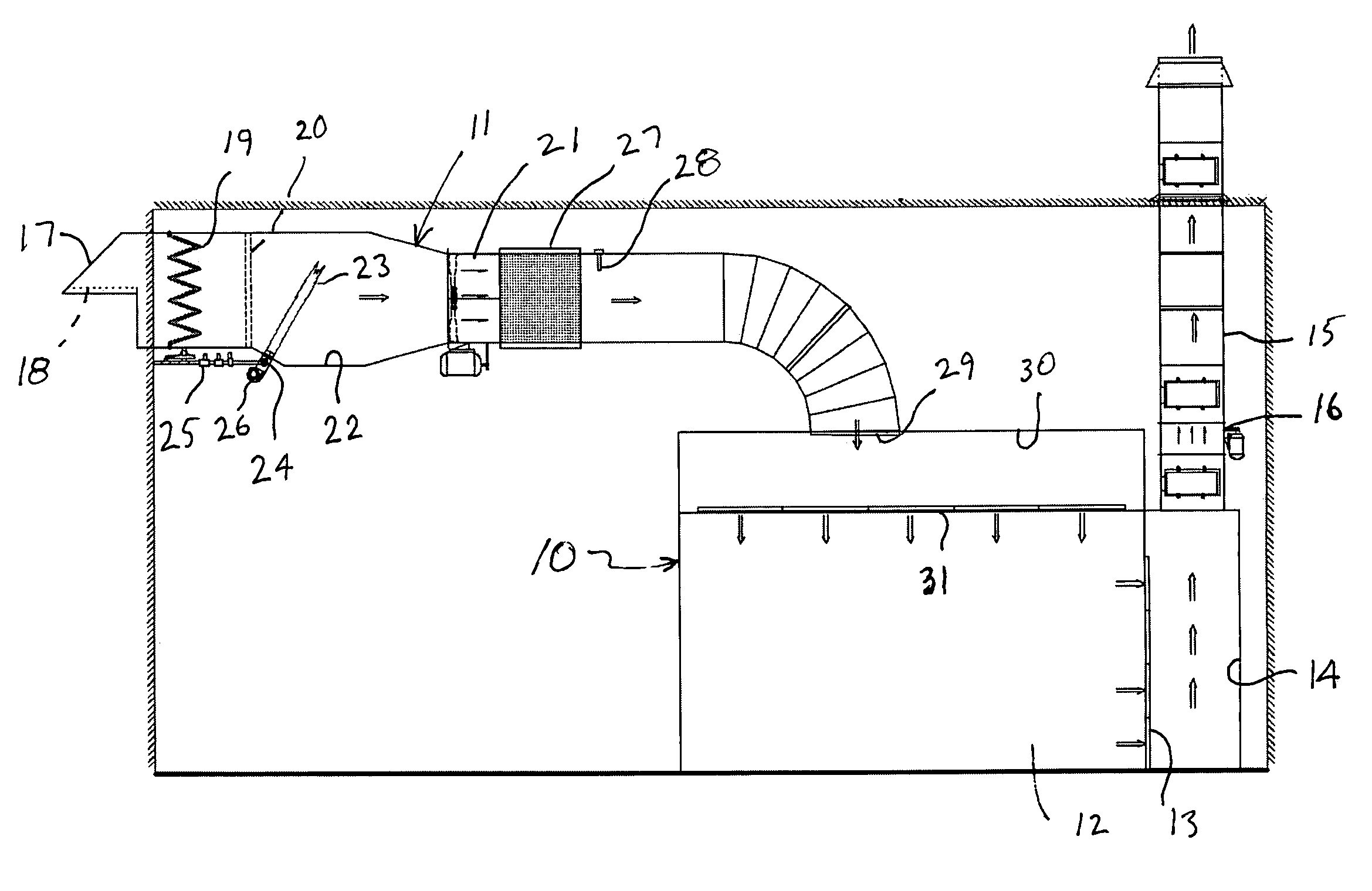
[0025]The invention is directed to a heated replacement air system for an industrial or commercial process, and to apparatus which allows for the independent adjustability of the replacement air volume flow and the BTU energy applied to that air volume flow. The system is described herein specifically for use with industrial and commercial spray paint booths. However, the system also can be used with similar processes where varying the air volume being moved through the system and the temperature of the air during some periods of the process might allow the process to still function well within all process and safety requirements.

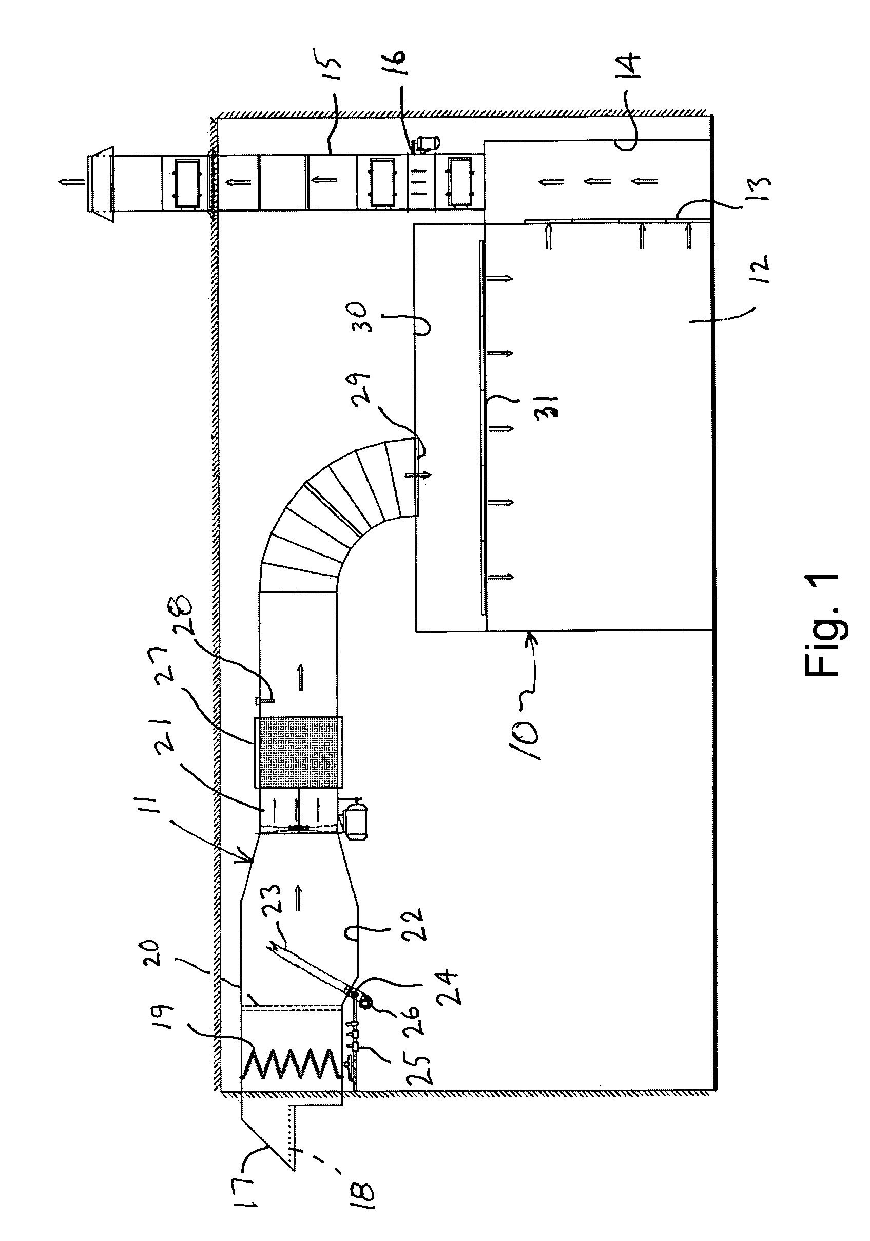
[0026]Turning to FIG. 1 of the drawings, an industrial paint spray booth 10 is shown incorporating a heated replacement air system 11 according to one embodiment of the invention. The spray booth 10 includes a work chamber 12 where objects are painted. The size of the chamber 12 will depend on the size of the objects which are painted. During painting, air ...


PUM


Abstract

Apparatus and a method for providing heated replacement air to a paint spray booth or other commercial process which requires heated make-up air to replace exhausted air. A blower draws outside air through a filter and an injection chamber prior to delivering the air to the process. Hot gases from a burner are injected into the injection chamber and mixed with the replacement air to adjust the temperature of the replacement air. The burner uses combustion air which is separate from the replacement air. The flow rate of the exhaust air and the replacement air can be adjusted to meet changing needs of the process. The BTU output from the burner is adjusted to maintain a desired replacement air temperature.

Description

CROSS-REFERENCE TO RELATED APPLICATIONS[0001]Applicants claim priority to U.S. Provisional Patent Application Ser. No. 60 / 556,097 filed Mar. 25, 2004.STATEMENT REGARDING FEDERALLY SPONSORED RESEARCH OR DEVELOPMENT[0002]Not Applicable.TECHNICAL FIELD[0003]The invention relates to a system for providing heated replacement air to a commercial or industrial process, such as to a paint spray booth.BACKGROUND OF THE INVENTION[0004]The process of applying atomized liquid coatings and adhesives generates potentially dangerous gaseous and particulate byproducts that are controlled or managed by confining them in an enclosure known as a spray booth and conveying them away from the process by entwining them in a moving air stream. This exhaust air stream typically passes through one or more stages of filtration to remove the particulates before the gaseous or vaporous byproducts are exhausted into the atmosphere. The volume of the exhaust air stream varies according to the size of the spray bo...

Claims


Application Information

Patent Timeline
Patent Type & Authority Patents(United States)
IPC IPC(8): F24H3/02B01D53/02B05B15/12
CPCB05B15/1222B05B16/60
Inventor KRUPP, DAVID
Owner SUPPLIER SUPPORT INT
Why Eureka
Try Eureka