
Adaptive resonant switching power system

a power system and resonant technology, applied in the direction of electric variable regulation, process and machine control, instruments, etc., can solve the problems of increasing the real estate consumption of the board or chip, introducing thermal losses, and adding significant design time and complexity to the layout of components, and achieves low heat dissipation, small heat sinks, and high efficiency.

Inactive Publication Date: 2008-04-22
APOGEE TECH
View PDF5 Cites 5 Cited by
  • Summary
  • Abstract
  • Description
  • Claims
  • Application Information

AI Technical Summary

Benefits of technology

The system achieves high efficiency (90% or greater) with low power losses and reduced heat dissipation, enabling smaller and less expensive designs, while minimizing radio frequency interference and simplifying circuit board layouts, allowing operation without a minimum load.

Problems solved by technology

However, in non-ideal conditions, the switching duty cycle is typically varied to provide voltage regulation as the input voltage varies.
Variation in the duty cycle causes at least one of the MOSFETs to turn off when it carries non-zero current or turn on with non-zero voltage thereby introducing thermal losses.
Patent, require a number of design compromises including increased real estate consumption on a board or chip.
Also, significant additional design time and complexity is added to component layout in order to place such a digital system in close proximity to the high frequency switching components in a resonant power converter.
Each of these disadvantages adds significant cost to any power converter using this technique which can make their use prohibitively expensive for many applications.

Method used


Image

  • Adaptive resonant switching power system
  • Adaptive resonant switching power system
  • Adaptive resonant switching power system

Examples


Embodiment Construction

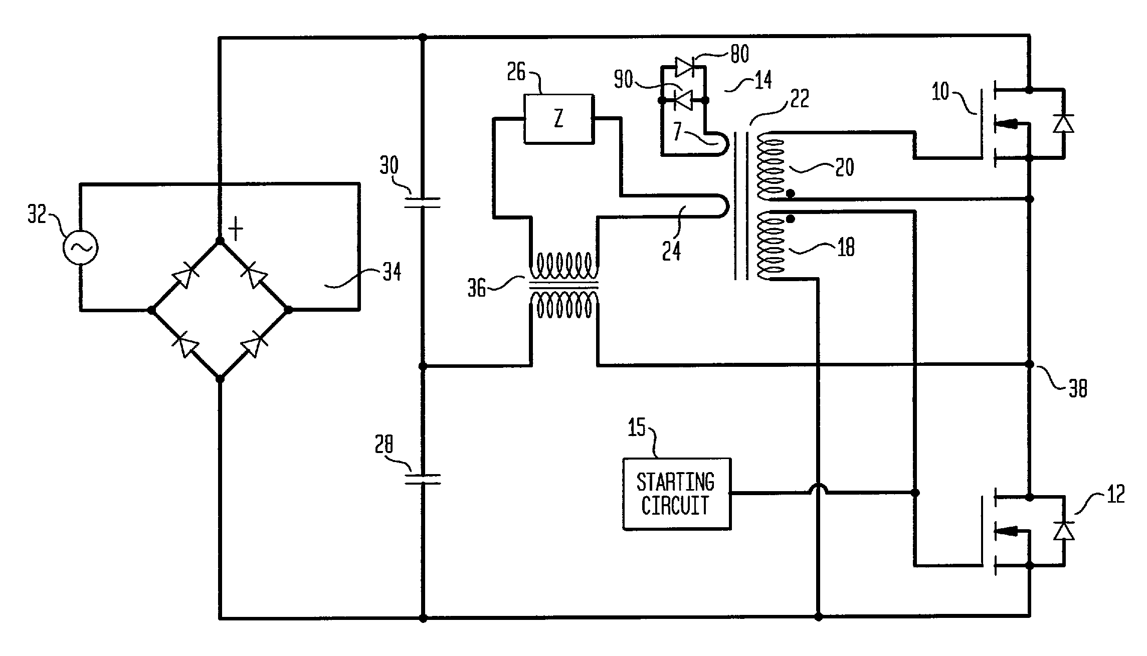
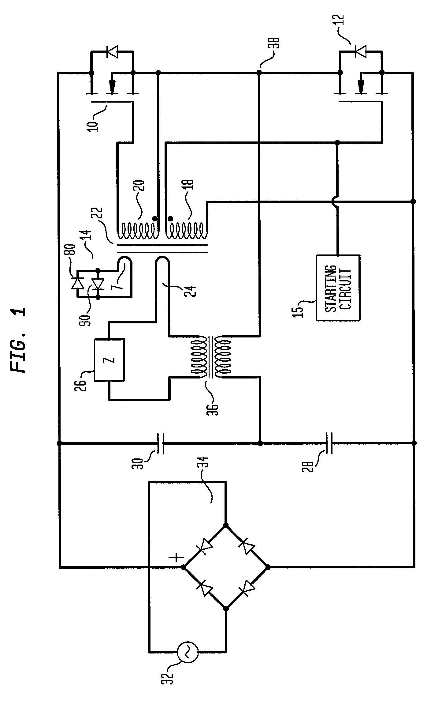
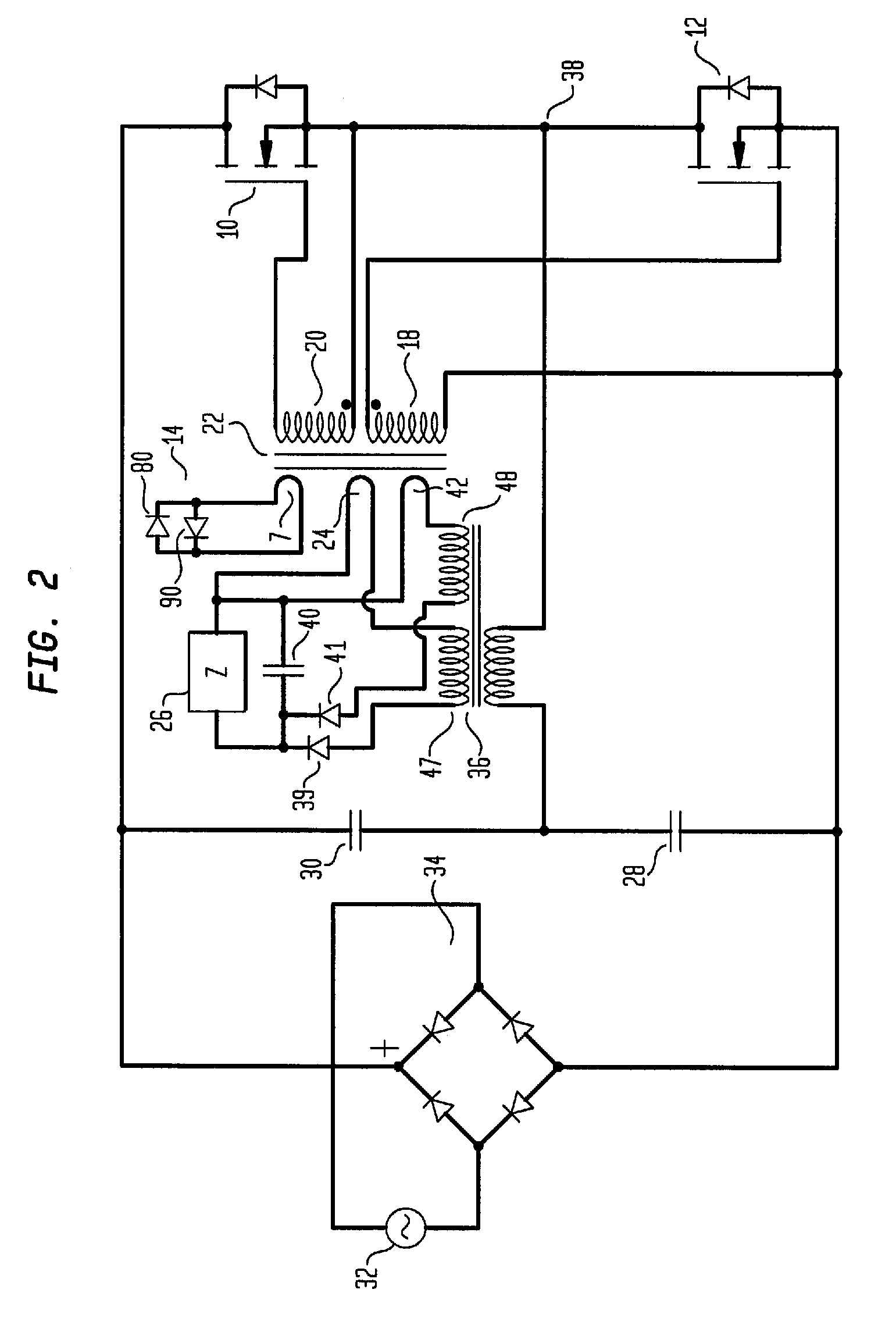
[0027]An illustrative embodiment of the present invention is described with reference to FIG. 1. A gate drive transformer 14 includes a core 22, primary coil 24, two secondary coils 20, 18, and an auxiliary coil 7. The primary coil 24 is connected between the load and the secondary of transformer 36. The first secondary coil 20 is connected between the gate and source of first MOSFET 10, the secondary coil 18 is connected between the gate and source of second MOSFET 12. The auxiliary coil 7 is connected across a pair of rectifier diodes 80, 90. A rectified power source from an AC input 32 through a bridge rectifier 34 is connected between the source of second MOSFET 12 and the drain of first MOSFET 10. A pair of capacitors 30, 28 are also connected in series with each other and in parallel with the MOSFETs across the rectified power input. The source of the first MOSFET 10 is connected to the drain of the second MOSFET 12 at a common node 38. A sensor coil 24 is included in the prim...


PUM


Abstract

A resonant switching power system operates with two resonant frequencies. A first frequency depends on the secondary leakage inductance of an output transformer and capacitor. The first frequency varies with changes in the load because load changes alter the leakage inductance. A second resonant frequency depends on the gate source capacitance of two MOSFET power devices in the circuit and the leakage inductance of the circuit's driving transformer. Power is thereby supplied that is always in phase with the load so that switching in the power supply occurs when current is near zero. High thermal efficiency is thereby achieved.

Description

CROSS REFERENCE TO RELATED APPLICATION[0001]This Application Claims Priority To U.S. Provisional Patent Application No. 60 / 437,584 Filed Dec. 31, 2002FIELD OF THE INVENTION[0002]The present invention relates to power supply circuits and more particularly to a power converter having a first resonant frequency dependent upon leakage inductance of an output transformer and capacitor and a second resonant frequency dependent upon gate source capacitance of the circuit's power MOSFETs and leakage inductance of a driving transformer.BACKGROUND OF THE INVENTION[0003]Power conversion devices known in the art such as resonant DC-to-DC power converters are used to provide power in audio applications and in a number of other electronic applications. A popular type of resonant power converters is the well known class D power converter.[0004]Class D converters operate by alternatively turning on and off a pair of power MOSFETs (metal oxide semiconductor field effect transistors) in response to a...

Claims


Application Information

Patent Timeline
Patent Type & Authority Patents(United States)
IPC IPC(8): H02M3/335H02M1/088H02M3/338
CPCH02M1/088H02M3/3382H03F3/217H02M2007/4818Y02B70/1491Y02B70/1433Y02B70/1441H02M2001/0058Y02B70/10H02M1/0058H02M7/4818H02M3/335H02M3/28H02M3/338
Inventor TSUI, PINGDANIELSON, MICHAEL S.
Owner APOGEE TECH
Learn More