Using common mode differential data signals of DDR2 SDRAM for control signal transmission

a technology of ddr2 and differential data, applied in the direction of information storage, static storage, digital storage, etc., can solve the problem of greatly increasing latency

Active Publication Date: 2008-04-22
META PLATFORMS INC
View PDF5 Cites 0 Cited by
  • Summary
  • Abstract
  • Description
  • Claims
  • Application Information

AI Technical Summary

Problems solved by technology

However, latency is greatly increased as a trade-off.

Method used


Image

  • Using common mode differential data signals of DDR2 SDRAM for control signal transmission
  • Using common mode differential data signals of DDR2 SDRAM for control signal transmission
  • Using common mode differential data signals of DDR2 SDRAM for control signal transmission

Examples


Embodiment Construction

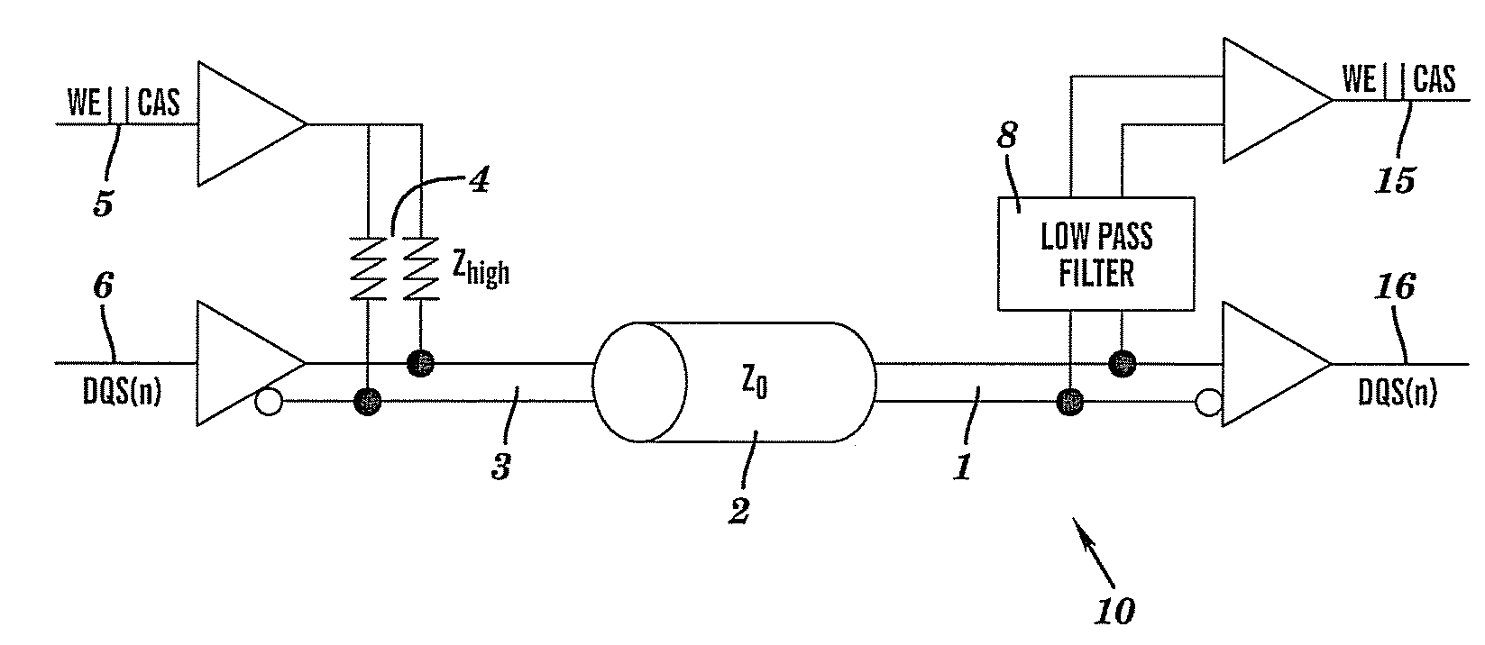
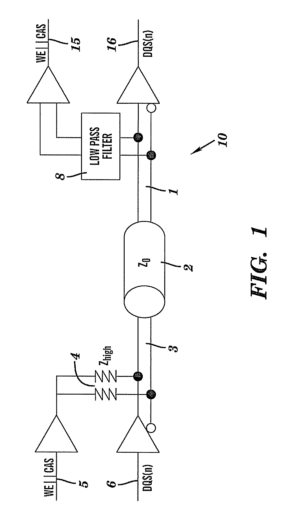
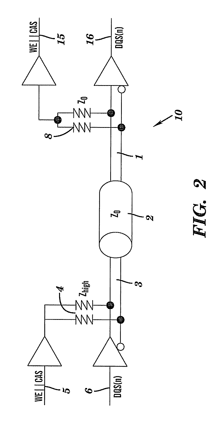
[0019]The teachings herein provide for a high-speed differential signaling scheme for double-data-rate two synchronous dynamic random access memory (DDR2 SDRAM, or DDR2). The signaling scheme varies a common-mode voltage, thus causing the common-mode voltage to transmit a logical signal. The operating voltage for the memory circuit disclosed herein ranges from about 0 volts to about 1.8 volts.

[0020]In the typical embodiment, slower DDR2 control signals (RAS / CAS etc.) are not structured using separate input paths and output paths (I / O's), but are transmitted via the common-mode of the higher speed differential signals. Using this design, the number of package pins and package / board wiring lanes required to implement DDR2 memory are reduced when compared to prior art designs for DDR2.

[0021]The teachings herein provide a high speed differential receiver having a common-mode that can be varied at a desired lower speed without effecting signal integrity of a received high speed signal. A...


PUM


Abstract

A double-data-rate two synchronous dynamic random access (DDR2) memory circuit includes a low-speed input path and a high-speed input path coupled thereto by an input coupling and forming a common input, the common input coupled to a memory core, the memory core having a common output wherein a high-speed output path and a low-speed output path are coupled together by an output coupling and further coupled to the common output of the memory core.

Description

BACKGROUND OF THE INVENTION[0001]1. Field of the Invention[0002]This invention relates to design of memory circuits and particularly to an enhancement for DDR2 memory.[0003]2. Description of the Related Art[0004]One advantage of DDR2 memory structures is the ability to use clock speeds that are higher than typically found in DDR SDRAM (double-data-rate synchronous dynamic random access memory).[0005]DDR SDRAM achieves greater bandwidth than ordinary SDR SDRAM (single-data-rate) by transferring data on both the rising and falling edges of the clock signal, and is considered “double pumped.” This effectively nearly doubles the transfer rate without increasing the frequency of the front side bus. Thus a 100 MHz DDR system has an effective clock rate of 200 MHz when compared to equivalent SDR SDRAM.[0006]DDR2 is the new generation of DDR technology. The primary benefit is the potential for faster throughput. In addition, the DDR2 improves the power consumption of the DIMM because it wor...

Claims


Application Information

Patent Timeline
Patent Type & Authority Patents(United States)
IPC IPC(8): G11C8/00
CPCG11C5/063G11C7/1048G11C7/1066
Inventor BARTLEY, GERALD K.BECKER, DARRYL J.DAHLEN, PAUL E.GERMANN, PHILIP R.MAKI, ANDREW B.MAXSON, MARK O.
Owner META PLATFORMS INC
Why Eureka
Try Eureka