Camera model and calibration procedure for omnidirectional paraboloidal catadioptric cameras

a catadioptric camera and camera technology, applied in image enhancement, instruments, printers, etc., can solve the problems of limiting the placement and size of the mirror, the difficulty of achieving perfect orthographic projection with current lens and camera technology, and the slight undesired perspective projection, etc., to achieve the effect of improving the calibration model of the omnidirectional camera

Inactive Publication Date: 2008-04-22
LUCENT TECH INC
View PDF5 Cites 19 Cited by
  • Summary
  • Abstract
  • Description
  • Claims
  • Application Information

AI Technical Summary

Benefits of technology

[0009]The present invention provides a system and method for calibrating an omnidirectional paraboloidal catadioptric camera based on a model, which does not assume an ideal projection system for the camera. In

Problems solved by technology

In practice, it is difficult to achieve a perfect orthographic projection with current lens and camera technologies.
This may result, for example, in a slight undesired perspective projection in addition to mirror misalignment and radial distortion of the lens.
A camera implementation using a telecentric lens or a camera implementation using a zoom lens combined with magnification lenses may produce close to ideal orthographic projections but both severely limit the placement and size of the mirror.
Thu

Method used


Image

  • Camera model and calibration procedure for omnidirectional paraboloidal catadioptric cameras
  • Camera model and calibration procedure for omnidirectional paraboloidal catadioptric cameras
  • Camera model and calibration procedure for omnidirectional paraboloidal catadioptric cameras

Examples


Embodiment Construction

Ideal Paraboloidal Catadioptric Camera Model

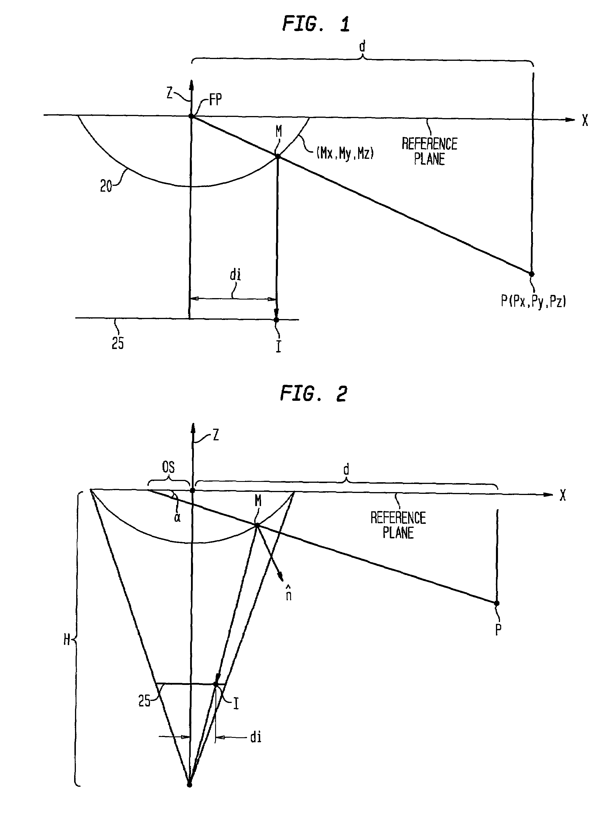
[0020]An ideal model for a paraboloidal catadioptric camera is illustrated in FIG. 1. In a 3D environment, described by a coordinate system (x, y, z), a ray of light radiating from a given point P (px, py, pz) reflects off of point M (mx, my, mz) on the paraboloidal mirror 20, and projects onto the image plane 25 at point I. Since the paraboloidal mirror 20 is symmetric about the z-axis, point M may be represented as (mr, θ, mz) and P as (pr, θ, pz), where mr=√{square root over (mx2+my2)}, pr=√{square root over (px2+py2)}, and θ is the angle between the projection of the light ray onto the xy-plane and the x-axis. The reference plane of FIG. 1, which lies in the xy-plane, is perpendicular to the central axis of the paraboloidal mirror and goes through the focal point of the parabola. The camera image plane 25 is parallel to the aforementioned xy-plane. Since the profile of the mirror corresponds to the parabola

[0021]mz=mr22⁢r-r2

(where r is...


PUM


Abstract

A paraboloidal catadioptric camera is calibrated by relaxing the assumption of an ideal system to account for perspective projection, radial distortion, and mirror misalignment occurring within the camera system. Calibration points, which are small and visually distinct objects, are distributed at fixed locations within an environment. Omnidirectional images are captured by the catadioptric camera at different locations of the environment. Data points are obtained by identifying the location of the calibration points in each captured image. An optimization algorithm best-fits the data points to a perspective camera model in order to derive parameters, which are used to calibrate the catadioptric camera.

Description

CROSS-REFERENCE TO RELATED APPLICATIONS[0001]This application claims the benefit of U.S. Provisional Application No. 60 / 294,061 filed May 29, 2001, the contents of which are hereby incorporated by reference in its entirety. This application is related to U.S. patent application Ser. No. 10 / 122,337 filed on Apr. 16, 2002 by the same named inventors of the present application, the contents of which are hereby incorporated by reference in its entirety.BACKGROUND OF THE INVENTION[0002]The present invention relates to the generation of omnidirectional images, and more particularly, to a calibration model for an omnidirectional camera.DESCRIPTION OF THE RELATED ART[0003]Omnidirectional still and video cameras have become increasingly popular in applications such as telepresence, three-dimensional (3D) reconstruction, and autonomous navigation. Omnidirectional images can be created by several techniques, not all of which create images from a single center-of-projection (COP). One family of...

Claims


Application Information

Patent Timeline
IPC IPC(8): G03B37/00G03B43/00H04N17/00G02B13/06G06T5/00G06T7/00
CPCG02B13/06G06T5/006G06T7/0018G06T7/80
Inventor ALIAGA, DANIEL G.CARLBORN, INGRID B.
Owner LUCENT TECH INC
Why Eureka
Try Eureka