Low chamfer angled torque tube end fitting with elongated overflow groove

a torque tube and end fitting technology, applied in the field of torque tube and a manufacturing method of torque tube, can solve the problems of reducing the fatigue life of a component, corrosive inhibiting surface coating is negatively affected, fatigue cracking, etc., to increase the axial and torque load strength, reduce the weight of the tube, and reduce the effect of fatigue li

Inactive Publication Date: 2008-04-29
THE BOEING CO
View PDF15 Cites 13 Cited by
  • Summary
  • Abstract
  • Description
  • Claims
  • Application Information

AI Technical Summary

Benefits of technology

[0013]The present invention has several advantages over existing torque tube manufacturing methods. One advantage provided by an embodiment of the present invention is the provision of a torque-transmitting coupling having an associated tube arc length that is approximately equal in length to a formed chamfer area length of the chamfer surface and the elongated overflow groove of the coupling. This provides a torque tube with uniform wall thicknesses over chamfer areas that are not in tension or compression. Such provision provides a torque tube with increased fatigue life, increased axial and torque load strength, minimizes tube weight, allows for increased tube material variation, and decreases end fitting manufacture costs and torque tube raw material costs.
[0014]Another advantage provided by an embodiment of the present invention is the provision of having chamfer areas with chamfer angles of approximately 20°. This provides a torque tube with increased strength and less susceptibility to cracking in the chamfer areas, thus providing a torque tube with increased fatigue life.
[0015]Yet another advantage provided by an embodiment of the present invention is the provision of a manufacturing method that contains a decreased amount of manufacturing steps by eliminating a need for heat treating, subsequent chilling of, hand straightening of, and minimizing natural aging time of the elongated tube. The present invention by reducing the amount of manufacturing steps not only decreases production cycle time and manufacturing costs but also eliminates disadvantages associated with the eliminated steps.
[0016]A further advantage provided by an embodiment of the present invention is the provision of elongated overflow grooves within a torque tube, which further increase strength and prevent cracking in the walls of the torque tube for increased fatigue life.

Problems solved by technology

Thinning occurs in the elongated tube near the notches and can cause fatigue cracking over time.
Cracking, as known in the art, reduces fatigue life of a component and is therefore undesirable.
A disadvantage with heat treating the elongated tubes is that the corrosive inhibiting surface coating is negatively affected during the heat treatment.
Due to stretching and thinning of the tube walls, the tubes are weakened and are susceptible to cracking under fatigue.
Thinning can be difficult to detect by ordinary inspection procedures without destructive testing.
The above-mentioned process of manufacturing a torque tube is time consuming and costly due the amount of steps within the process and the requirements for each step.

Method used


Image

  • Low chamfer angled torque tube end fitting with elongated overflow groove
  • Low chamfer angled torque tube end fitting with elongated overflow groove
  • Low chamfer angled torque tube end fitting with elongated overflow groove

Examples


Embodiment Construction

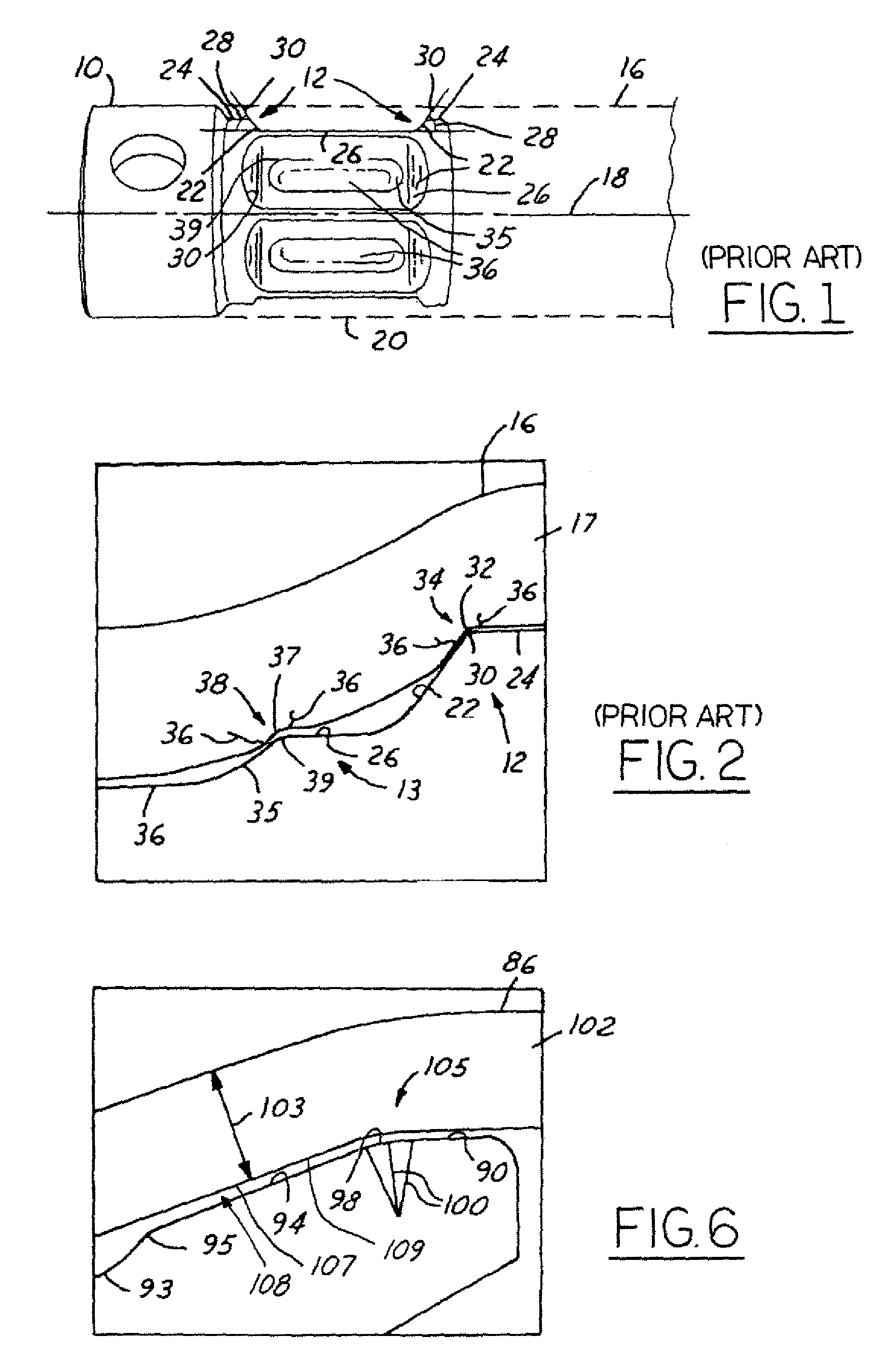
[0033]Referring now to prior art FIGS. 1 and 2, a perspective view of an end fitting 10 and a cross-sectional close-up view of chamfer areas 12 and groove areas 13 of a traditional torque tube 14 are shown. The torque tube 14 has an elongated cylindrical tube 16 having a tube wall 17 and a longitudinal axis 18 extending through a center of and along length of the tube 16. An end 20 of the elongated tube 16 is coaxially formed and fixed onto the fitting 10. Only one end 20 of the elongated tube 16 is shown, typically, a second end of the elongated tube is formed and fixed to a second fitting, similar to fitting 10.

[0034]The fitting 10 has multiple chamfered surfaces 22, between a pair of upper flat surfaces 24 and multiple lower flat surfaces 26, with chamfer angles 28 that are approximately 45° relative to the lower surfaces 26. The upper surfaces 24 transition to the chamfer surfaces 22 at relatively sharp chamfer edges 30. The chamfer edges 30 correspond with upper notches 32 that...


PUM

PropertyMeasurementUnit
chamfer angleaaaaaaaaaa
angleaaaaaaaaaa
chamfer angleaaaaaaaaaa

Abstract

A method of forming a torque-transmitting coupling (193) includes forming at least one fitting (192) having a tube conforming area (200). The forming area (200) includes a material overflow groove (194) and multiple flat surfaces (202). The forming area (200) has an associated tube arc length that is approximately equal in length to a formed area length of the flat surfaces (202) with the elongated overflow groove (194). An elongated tube (190) is procured. The elongated tube (190) is formed onto the tube conforming area (200) to form the torque-transmitting coupling (193).

Description

BACKGROUND OF INVENTION[0001]The present application is a continuation-in-part of U.S. patent application Ser. No. 10 / 253,564, filed on Sep. 24, 2002 now U.S. Pat. No. 6,932,118, entitled “Lower Chamfer Angled Torque Tube End Fitting”, which is incorporated by reference herein.[0002]The present invention relates generally to vehicle systems, and more particularly, to a torque tube and a method of manufacturing the torque tube.[0003]Torque tubes are typically used for mechanically transmitting torque from a power drive unit to a rotating device that provides translation motion. For example, a torque tube is commonly used in a ground-based vehicle to transfer torque from an engine to a front or rear axle, which in turn rotates the wheels of the vehicle to provide propulsion. Another example application is in an aircraft whereby a torque tube may be utilized for the transmitting of torque between a power drive unit and a ballscrew, which provides either horizontal or vertical translati...

Claims


Application Information

Patent Timeline
Patent Type & Authority Patents(United States)
IPC IPC(8): F16L9/00B23P25/00F16D1/104
CPCF16D1/072F16D1/104Y10T403/7035Y10T74/2188Y10T403/4991Y10T29/49885Y10T29/49803
Inventor SAHA, PRADIP K.BERDEN, MATTHEW J.
Owner THE BOEING CO
Why Eureka
Try Eureka