Wind driven power generator

a technology of wind power generator and wind power, which is applied in the direction of electric generator control, renewable energy generation, greenhouse gas reduction, etc., can solve the problems of airborne wildfowl hazard, increased needs and costs associated with generator development, etc., to reduce the risk of airborne wildfowl, and improve efficiency

Inactive Publication Date: 2008-04-29
BROADSTAR INVESTMENT COMPANY
View PDF21 Cites 44 Cited by
  • Summary
  • Abstract
  • Description
  • Claims
  • Application Information

AI Technical Summary

Benefits of technology

[0004]The present invention also provides a wind driven power generator which includes a unique rotor or propeller configuration, is compact and less obtrusive than conventional airscrew or propeller type generators and includes a rotor which may be disposed within a shroud or duct for efficiency improvements while minimizing hazards to bird life and while being less susceptible to performance degradation or structural problems associated with ice or snow accumulation, for example.
[0009]In accordance with yet a further aspect of the present invention a wind driven power generator is provided wherein a rotor which is responsive to wind flowing thereover rotates within a duct or shroud to improve rotor efficiency, and minimize the adverse effects of rain, or snow or ice accumulation on the rotor or flow of such through the duct. The duct is particularly advantageous in that there are provided paths for the flow of cooling air over one or more electric generators connected to the rotor. Still further, the rotor duct or shroud is preferably configured to accelerate the flow of air through the duct and the duct is also configured to modify or improve the weather vaning tendency of the generator so that the duct opening is normally oriented to take advantage of the direction of the wind.

Problems solved by technology

Wind driven power generators are under intensive development as energy needs and the costs associated therewith continue to escalate.
With the development of wind driven power generators certain needs have become apparent, including the need to provide a generator which overcomes the disadvantage of conventional airscrew or propeller type generators which must be mounted at a substantial height above the surface, are not aesthetically pleasing, are a hazard to airborne wildfowl, and are susceptible to ice accumulation on the propeller blades.

Method used


Image

  • Wind driven power generator
  • Wind driven power generator
  • Wind driven power generator

Examples


Embodiment Construction

[0026]In the description which follows, like parts are marked throughout the specification and drawings with the same reference numerals, respectively. The drawing figures may not be to scale and certain features may be shown exaggerated in scale or in somewhat schematic form in the interest of clarity and conciseness.

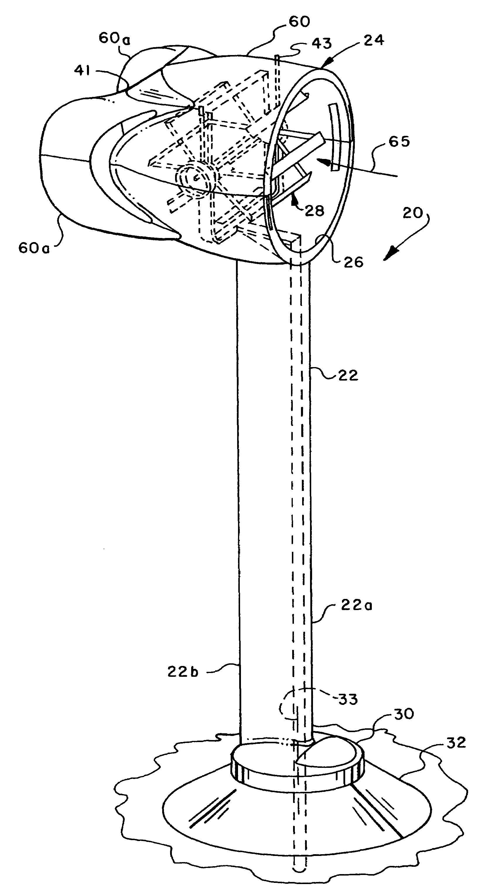
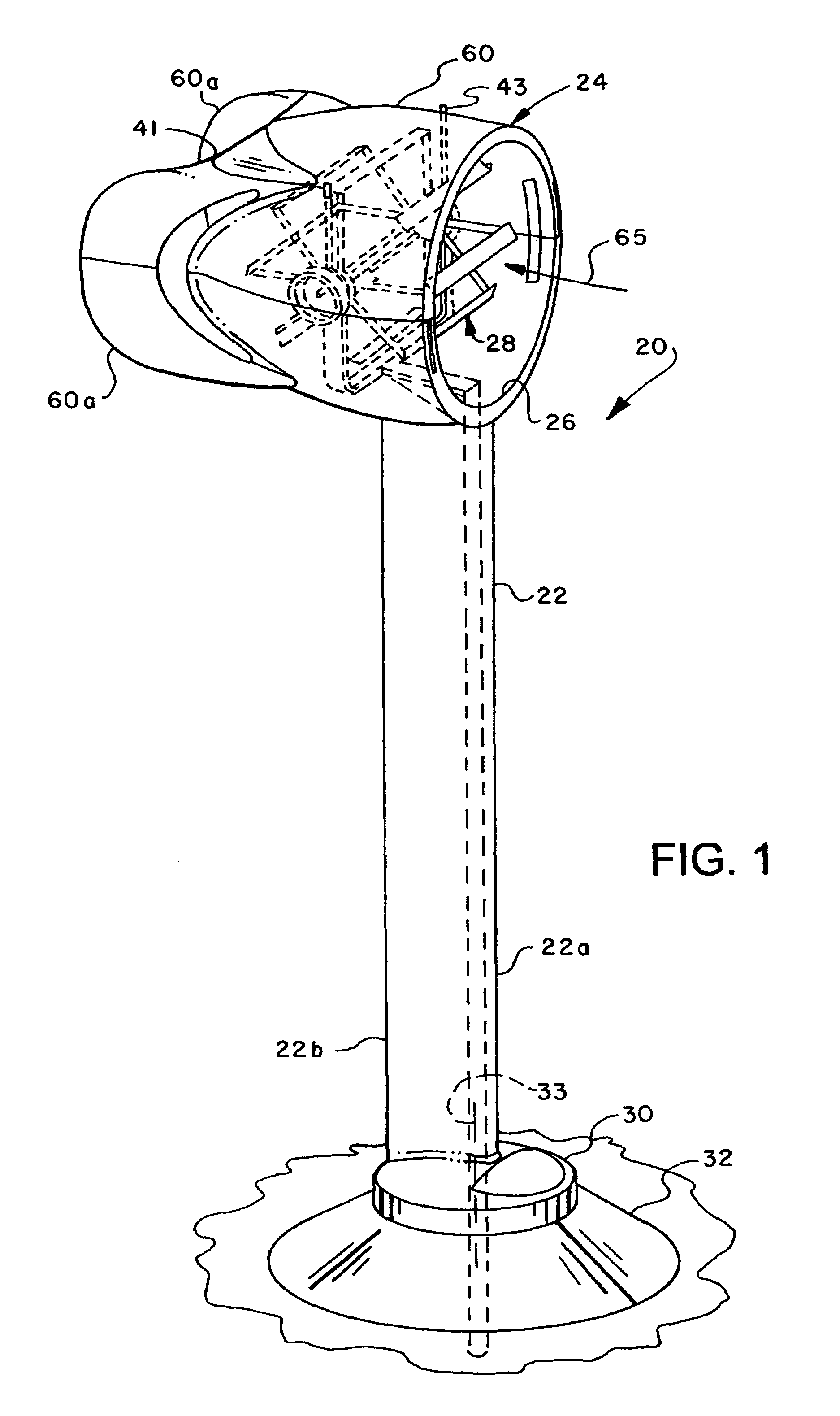
[0027]Referring to FIG. 1, there is illustrated a wind driven power generator in accordance with the invention and generally designated by the numeral 20. The power generator 20 is characterized by a vertically extending mast 22, preferably having a symmetrical airfoil shape in cross section, and supporting a generally cylindrical duct or shroud 24. Duct 24 has an air inlet 26 defining an opening oriented to allow natural air currents or wind to flow through said opening for propelling or driving a rotor, generally designated by the numeral 28. Rotor 28 may be of a type similar to that disclosed and claimed in my co-pending U.S. patent application Ser. No. 11 / 411,540 f...


PUM


Abstract

A wind driven generator includes a rotor disposed in a cylindrical duct and supported by a frame for rotation in response to wind flowing through the duct. The rotor includes plural circumferentially spaced paralleled rotor blades supported for rotation about a generally horizontal axis. Each blade is supported for pivotal movement to change blade pitch, angle of attack or camber as the rotor rotates. A pitch or camber control motor or self-governing wind vane mechanism is operable to move a circular cam to vary blade pitch or camber to control rotor speed. The duct is mounted on a mast having a base supported on a foundation for pivotal movement to face the wind for maximizing air flow through the duct. Electric power generators are connected to opposite ends of the rotor at respective power output or drive shafts.

Description

BACKGROUND OF THE INVENTION[0001]Wind driven power generators are under intensive development as energy needs and the costs associated therewith continue to escalate. With the development of wind driven power generators certain needs have become apparent, including the need to provide a generator which overcomes the disadvantage of conventional airscrew or propeller type generators which must be mounted at a substantial height above the surface, are not aesthetically pleasing, are a hazard to airborne wildfowl, and are susceptible to ice accumulation on the propeller blades.[0002]There has been a continuing need and desire for improvements in wind driven power generators, including the desire to overcome the shortcomings of conventional power generators such as those described hereinabove, while also providing a generator which is efficient, physically compact and is easily adapted to varying wind velocity conditions while retaining the capability of power generation. It is to these...

Claims


Application Information

Patent Timeline
Patent Type & Authority Patents(United States)
IPC IPC(8): F03D9/00
CPCE02D27/42F03D3/002F03D3/0427F03D3/068F03D11/04F05B2260/506Y02E10/728Y02E10/74F03D13/20E02D27/425F03D9/25F03D80/30F03D3/04F03D13/22
Inventor STEPHENS, THOMAS G.
Owner BROADSTAR INVESTMENT COMPANY
Why Eureka
Try Eureka