Hybrid magnet configuration

a hybrid magnet and configuration technology, applied in the direction of magnetic materials, cores/yokes, reradiation, etc., can solve the problems of magnet coil damage, magnet coil overheating, and inability to produce homogenous magnetic, etc., to achieve the effect of minimizing the magnetic fringe field, improving the suppression of fringe field, and facilitating individual adjustment of magnetic stray field

Active Publication Date: 2008-04-29
BRUKER BIOSPIN
View PDF17 Cites 4 Cited by
  • Summary
  • Abstract
  • Description
  • Claims
  • Application Information

AI Technical Summary

Benefits of technology

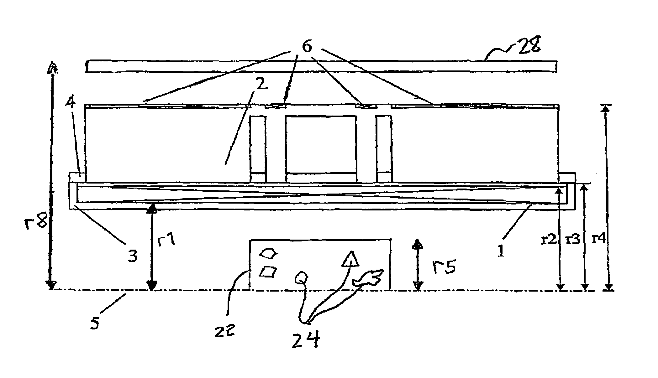
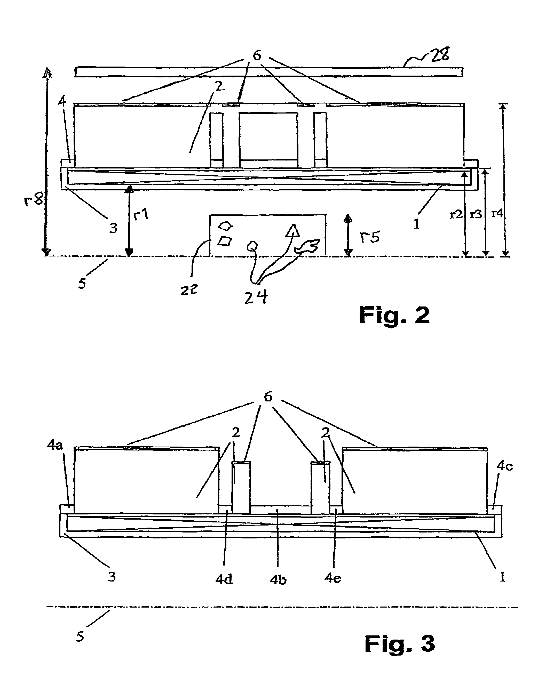
[0012]The magnet bodies surrounding the solenoid coil render the magnetic field in the investigational volume homogenous and also provide a feed-back for the flux generated by the solenoid coil. The magnet body(s) are thereby disposed relatively close to the axis of the solenoid coil (r3<1.3 r2). In this fashion, the magnetic field produced by the solenoid coil can be influenced to an extremely good extent by the magnet body. The influence of the magnet body on the magnetic field depends, in particular, on the structure of the magnet body. This structure can be effected both in a radially inward as well as the radial outward region of the magnet body. In particular, through the positioning as well as the shaping of the magnet body in its radially inner region, it is possible to compensate for the inhomogeneities of the magnetic field produced by the solenoid coil. The choice of the outer radius r4 of the magnet body has substantial influence on the spatial limitation of the magnetic field so that the fringe field produced by the solenoid coil can be reduced through a suitable choice of parameters even without using a shielding coil made from a super-conducting material. Use of a simple solenoid coil allows the magnetic forces on the coil windings to be controlled to an improved extent such that the field strength at which the magnet quenches can be substantially increased. In this manner, it is possible to increase the strength of the current flowing through the windings as well as the magnetic field produced thereby and / or to produce a given magnetic field of a given strength using a magnet configuration having a reduced number of windings and using higher current to thereby reduce costs. The magnet configuration in accordance with the invention therefore presents possibilities to produce a more homogenous field which is suitable for a measurement of magnetic resonance using a reliable solenoid coil.
[0041]In a variation, a (smaller) positive or negative current is introduced into the additional windings and superconductingly short circuited to realize improved fringe field suppression.

Problems solved by technology

However, solenoid coils are not suitable for production of homogenous magnetic fields, since this simple geometry has, up to this point, not been capable of compensating for the interfering coefficients h2, h4, . . . . It is therefore conventional in the art to use solenoid coils having one or more notches in order to produce homogenous magnetic fields with such windings.
A substantial disadvantage of utilization of magnet coils having notches which, in practice, are fashioned by rings filled up with a solid material, is that the bordering windings made from superconducting wire can undergo a transition into the normally conducting state in response to the large magnetic forces which lead to friction or other relaxation phenomena in the bordering region.
As a result thereof, an overheating of the normally conducting regions can occur and, in extreme cases, the magnet coil can be destroyed.
This makes, in particular, the production of extremely high magnetic fields difficult or makes the magnetic coil more expensive, since one is forced to limit the current strength through the wires in order to keep the magnetic forces which act on the superconducting wire in the regions bordering a notch sufficiently small.
The magnet configuration is consequently provided with a correspondingly greater number of windings of expensive superconducting wire and the entire configuration becomes radially larger, which finally limits the maximum achievable magnetic induction in the investigational volume.
An additional problem with magnet configurations is that they produce highly undesirable magnetic fringe fields in a region of up to 10 m about the magnet configuration.
However, towards this end, additional windings of superconducting wire are required as well as a support body for the shielding windings as a result of which the magnet configuration becomes more complicated, larger, and more expensive.
This configuration has the disadvantage that the weight of the magnet configuration is very high due to the large ferromagnetic cylindrical jacket and, in addition, produces an undesirable influence on the homogeneity of the field.

Method used


Image

  • Hybrid magnet configuration
  • Hybrid magnet configuration
  • Hybrid magnet configuration

Examples


Embodiment Construction

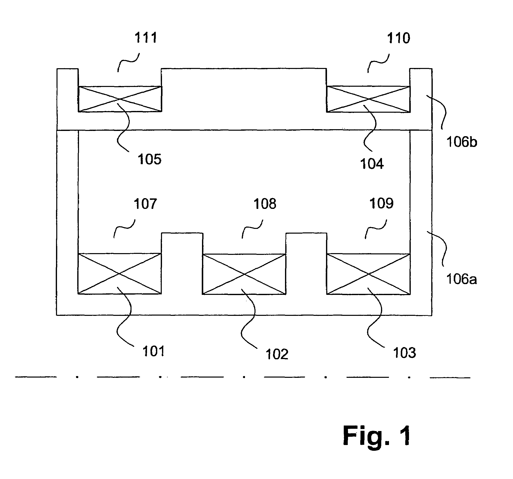
[0056]FIG. 1 shows the principal components of a conventional rotationally symmetric magnet coil configuration. Winding chambers 107, 108, 109, 110, and 111 are fashioned into a two-part support body 106a, 106b. First magnet windings 101, 102, 103 and second magnet windings 104, 105, each made from superconducting coil wire, are wound in these winding chambers. First magnet windings 101, 102, 103 serve primarily to produce a strong magnetic field in an investigational volume which surrounds, e.g. in a magnetic coil configuration for a magnetic resonance apparatus, the symmetry center of the magnet coil configuration. The second magnet windings 104, 105 primarily serve for minimizing the fringe magnetic field in an outer region of the magnet coil arrangement by means of a feedback of the magnetic flux (active shielding). The direction of the electrical current in the second magnet windings 104, 105 is therefore opposite to the direction of the electrical current in the first magnet w...


PUM


Abstract

A co-axial magnet configuration for the production of a magnetic field and investigational volume which is suitable for measurement of magnetic resonance has at least one superconducting solenoid coil or solenoid coils which are radially nested within each other, wherein the windings of the solenoid coil(s) in a radial region about the axis of the magnetic configuration are disposed between r1 and r2, wherein r1<r2 is characterized in that the windings are surrounded by at least one rotationally symmetric magnet body made from ferromagnetic material which extends over a radial region between r3 and r4 wherein r3<r4 wherein r2<r3<1.3 r2 and r4>1.3 r3, wherein the rotationally symmetric magnet body or bodies are structured, dimensioned and positioned in such a fashion that the magnetic field is homogenized in the investigational volume and the magnetic fringe field outside the magnet configuration is essentially suppressed to permit the production of strong magnetic fields of high homogeneity without requiring notches in the coil configuration.

Description

[0001]This application claims Paris Convention priority of DE 10 2004 007 291.4 filed Feb. 14, 2004 the entire disclosure of which is hereby incorporated by reference.BACKGROUND OF THE INVENTION[0002]The invention concerns a coaxial magnet configuration for production of a magnetic field in an investigation of volume which is suitable for measurement of magnetic resonance with at least one superconducting solenoid coil or with solenoid coils which are radially nested within each other, wherein the windings of the solenoid coil (s) in a radial region about the axis of the magnet configuration are disposed between r1 and r2 wherein r1>r2.[0003]The magnetic field h(z) as a function of the coordinate z on the axis of a magnet system of this kind can be generally expressed as follows:h(z)=h0+h1z+h2z2+h3z3+h4z4+h5z5+h6z6+[0004]The term h0 thereby represents the desired position independent and therefore homogenous magnetic field. The additional terms with the coefficients h1, h2 . . . ...

Claims


Application Information

Patent Timeline
Patent Type & Authority Patents(United States)
IPC IPC(8): G01V3/00G01R33/3815G01R33/3873G01R33/3875
CPCG01R33/3815G01R33/3873G01R33/3875
Inventor WESTPHAL, MICHAEL
Owner BRUKER BIOSPIN
Why Eureka
Try Eureka