Internal voltage generator

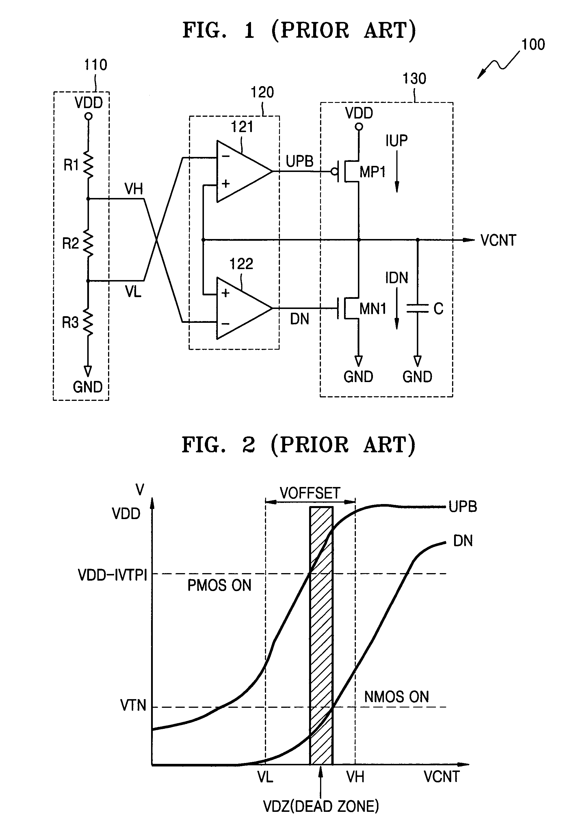
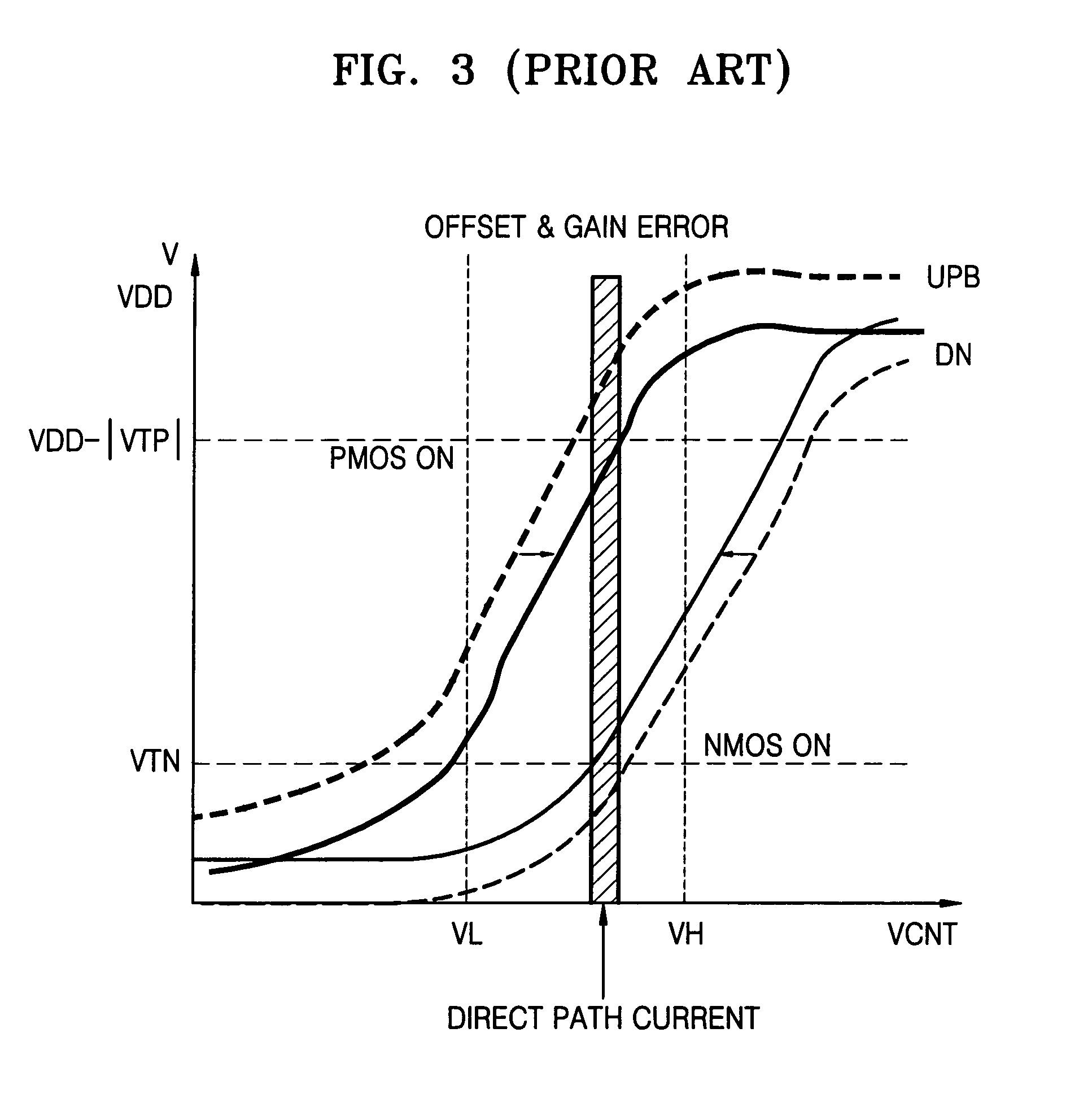
a voltage generator and internal voltage technology, applied in the field of internal voltage generators, can solve the problems of wasting power, difficult to produce internal voltage vcnts having a designated voltage level, and the internal voltage generator b>100/b> of fig. 1 also has another problem

Active Publication Date: 2008-04-29
SAMSUNG ELECTRONICS CO LTD
View PDF21 Cites 15 Cited by
  • Summary
  • Abstract
  • Description
  • Claims
  • Application Information

AI Technical Summary

Benefits of technology

[0021]The present invention provides an internal voltage generator that is greatly tolerant of variation generated in internal devices, such as transistors, due to deviations occurring in the manufacture of semiconductor memory devices.
[0022]The present invention also provides an internal voltage generator that can produce an internal voltage within a short setup time.

Problems solved by technology

The direct path of current is not necessary and causes a waste of power.
However, the widening of the offset section VOFFSET to improve the yield of a semiconductor device and to overcome offset and gain errors can lead to the following problems.
Second, an intermediate value of a wide offset section VOFFSET, which is used as a voltage level of the internal voltage VCNT, can change according to the accuracy of a process, so it is not easy to produce an internal voltage VCNT having a designated voltage level.
The internal voltage generator 100 of FIG. 1 also has another problem, in the form of setup time.
However, since the sizes of the two MOS transistors MP1 and MN1 are set during manufacturing, the amount of current that flows cannot be arbitrarily controlled.

Method used


Image

  • Internal voltage generator
  • Internal voltage generator
  • Internal voltage generator

Examples


Embodiment Construction

[0066]The attached drawings for illustrating preferred embodiments of the present invention are referred to in order to gain a sufficient understanding of the present invention, the merits thereof, and the objectives accomplished by the implementation of the present invention. Hereinafter, the present invention will be described in detail by explaining preferred embodiments of the invention with reference to the attached drawings. Like reference numerals in the drawings denote like elements.

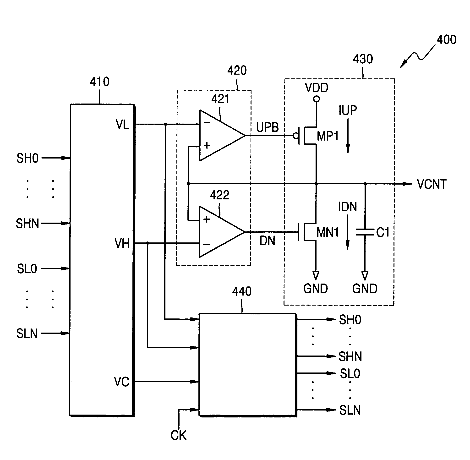
[0067]FIG. 4 is a block diagram of an internal voltage generator 400 according to an embodiment of the present invention. Referring to FIG. 4, the internal voltage generator 400 includes a reference voltage generation block 410, a comparator block 420, an output driving block 430, and an offset section control block 440.

[0068]The reference voltage generation block 410 outputs a first reference voltage VC, a second reference voltage VH, and a third reference voltage VL in response to a plurality o...


PUM


Abstract

An internal voltage generator is highly tolerant of electrical parameter changes of transistors occurring due to process deviation. The generator can produce an internal voltage within a short setup time when there is a significant difference between a voltage level of an internal voltage when power is initially supplied to the internal voltage generator and a voltage level of an internal voltage to be produced. In one embodiment, the internal voltage generator of the present invention includes a comparator block and an output driving block to produce an internal voltage. The internal voltage generator further includes a reference voltage generation block, which generates at least two reference voltages to be supplied to the comparator block, and an offset section control block, which supplies a control signal for optimizing an offset section, that is, a voltage difference between the reference voltages, to the reference voltage generation block. The internal voltage generator can further optionally include an auxiliary output driving block in addition to a main output driving block to reduce the setup time for which the internal voltage is produced when voltage is initially supplied and to reduce power consumption. The internal voltage generator further includes a first control signal generation block and a control block to control operations of the main and auxiliary output driving blocks.

Description

CROSS-REFERENCE TO RELATED PATENT APPLICATIONS[0001]This application claims the benefit of Korean Patent Application No. 10-2005-0024073, filed on Mar. 23, 2005, in the Korean Intellectual Property Office, the disclosure of which is incorporated herein in its entirety by reference.BACKGROUND OF THE INVENTION[0002]1. Field of the Invention[0003]The present invention relates to an internal voltage generator installed within a semiconductor memory device, and more particularly, to an internal voltage generator that prevents a center value in a Gaussian distribution of a produced internal voltage from largely moving even when a process parameter severely deviates during the manufacture of a semiconductor memory device, that reduces a setup time for an internal voltage, and that minimizes power consumption, thereby improving the yield.[0004]2. Description of the Related Art[0005]Semiconductor memory devices employ not only an external high supply voltage and an external low supply voltag...

Claims


Application Information

Patent Timeline
Patent Type & Authority Patents(United States)
IPC IPC(8): G05F1/10
CPCG11C5/14G11C29/02G11C29/021G11C29/028A63B37/12A63B37/14A63B37/0039B82Y99/00
Inventor LEE, SOON-SEOB
Owner SAMSUNG ELECTRONICS CO LTD
Why Eureka
Try Eureka