
Method of determining resonant frequency

a resonant frequency and frequency technology, applied in the field of oscillator, can solve problems such as affecting the sweep performance of torsion oscillators

Inactive Publication Date: 2008-04-29
LEXMARK INT INC
View PDF1 Cites 0 Cited by
  • Summary
  • Abstract
  • Description
  • Claims
  • Application Information

AI Technical Summary

Benefits of technology

[0003]The angle of the mirror moves sinusoidally with respect to time at a certain amount of sweep (termed amplitude), at a certain repetition rate (termed frequency), and with a potential lack of symmetry (termed median offset). The characteristics of mirrors can vary significantly due to physical variations from manufacturing tolerances and changing environmental conditions. Specifically, changes in air density affect drive efficiency, the resonant frequency of a torsion oscillator, and the ability to detect resonance. Thus, changes in elevation or other environmental parameters may affect the sweep performance of a torsion oscillator. The present invention is a method for controlling a torsion oscillator that reduces instances of off-resonant operation given changes in environmental conditions.
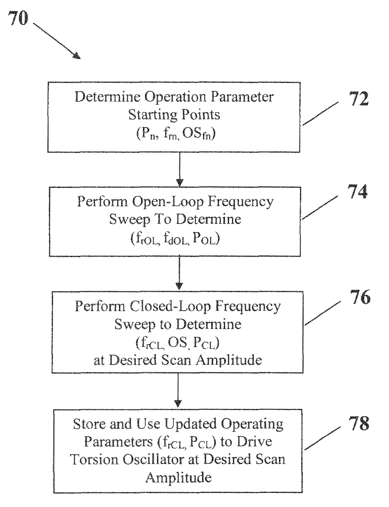
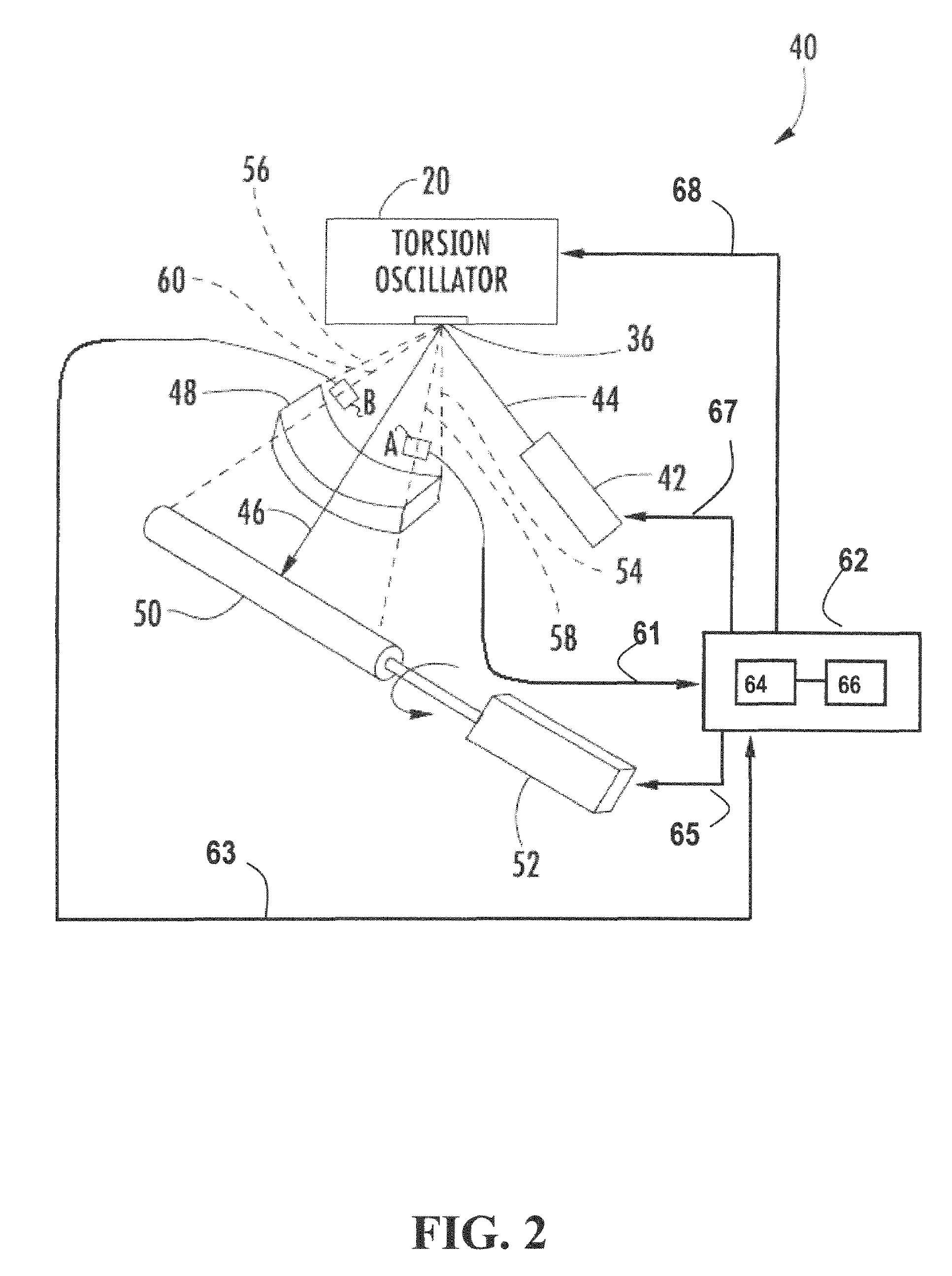
[0007]The imaging system monitors the closed-loop controller feedback while the torsion oscillator is operating in steady-state. This feedback may be incorporated into the drive level of the next open-loop resonant frequency sweep to ensure that the open-loop amplitude will continue to be approximately equal to the closed-loop steady-state amplitude. Making use of the closed-loop feedback in this manner helps ensure that the next open-loop resonant frequency sweep will not fail the open-loop vs. closed-loop amplitude check, which would result in a longer time to first print due to the need to repeat the open-loop sweep.

Problems solved by technology

Thus, changes in elevation or other environmental parameters may affect the sweep performance of a torsion oscillator.

Method used


Image

  • Method of determining resonant frequency
  • Method of determining resonant frequency
  • Method of determining resonant frequency

Examples


Embodiment Construction

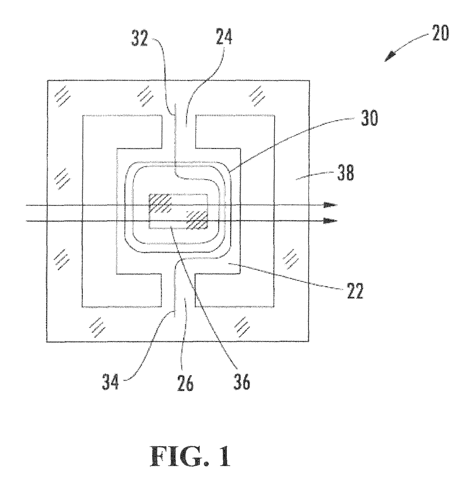
[0014]In many scanners and printers used with computers, data terminals, digital imaging systems, and similar devices, a light beam (preferably a laser beam) is reflected off a torsion oscillator minor to sweep a target. In very general terms, torsion oscillator construction is such that its motion is controlled by the characteristics of the electrical drive signal supplied to it, including the power level and the drive frequency. Specifically, in order to maintain stability the drive signal should be maintained substantially at the resonant frequency of the torsion oscillator.

[0015]A system for operating an imaging system typically includes a circuit for driving the system's torsion oscillator in a closed-loop scan amplitude control and at a substantially resonant frequency. The drive signal (also referred to as the “input signal”) may be any form of signal such as a sinusoidal signal, an impulse signal, a square wave signal or any other type of signal. Sensors are positioned along...


PUM


Abstract

A method for operating a torsion oscillator at its resonant frequency. The method performs an open-loop frequency sweep starting with nominal operation parameters saved from the factory or from a previous operation of the torsion oscillator. The sweep determines an open-loop resonant frequency and an open-loop drive level. A closed-loop resonant frequency sweep is performed and a closed-loop steady-state resonant frequency is determined. This frequency is used to calculate a closed-loop overshoot and a closed-loop steady-state drive level. The torsion oscillator is then operated in a closed-loop mode at the closed-loop steady-state resonant frequency and starting at the closed-loop steady-state drive level. Finally, the nominal operation parameters are updated and stored in non-volatile memory. The method minimizes the effects of ambient environmental conditions including air density on the steady-state operation of the torsion oscillator.

Description

FIELD[0001]This invention relates to the field of oscillating mechanisms. More particularly this invention relates to torsional oscillators and the systems used to drive torsional oscillators used in scanners, printers, and similar systems.BACKGROUND AND SUMMARY[0002]Electro-mechanical oscillators may be used to drive electro-optical mechanisms such as printers, scanners, barcode readers and similar devices. A torsion oscillator, which is one type of oscillation device and may also be referred to as a resonant galvanometer, typically includes a mirror that is disposed on a plate that is cut or etched from a silicon wafer and supported on trunnions. In one embodiment, magnets are attached to the plate and when electric current passes through a nearby coil, a force is exerted on the magnets. This force is translated to the plate and causes oscillation of the plate which twists the trunnions. Other forces may be employed to make such a system oscillate, such as electric fields or mecha...

Claims


Application Information

Patent Timeline
Patent Type & Authority Patents(United States)
IPC IPC(8): H03B5/30G02B26/10H03L5/00H02K33/00
CPCG02B26/0841G02B26/105
Inventor BUSH, CRAIG PALMERKLEMENT, MARTIN CHRISTOPHER
Owner LEXMARK INT INC
Learn More