
Antenna system

Inactive Publication Date: 2008-04-29
QUINTEL CAYMAN LTD
View PDF66 Cites 14 Cited by
  • Summary
  • Abstract
  • Description
  • Claims
  • Application Information

AI Technical Summary

Benefits of technology

[0026]The antenna assembly conveniently includes respective signal distribution means associated with each sub-array for splitting and distributing signals across the elements of the associated sub-array. Preferably, each of said signal distribution means includes a splitter arrangement for distributing signals to one or more of said sub-arrays. Conveniently, the splitter arrangement is arranged to distribute signal strength of said signals to said sub-arrays in a substantially uniform distribution, thereby to increase antenna boresight gain.
[0027]In one embodiment, at least one output signal from said distribution means associated with a first sub-array is spatially combined or overlapped with at least one output signal from said distribution means associated with a third sub-array, thereby to provide first and second combined output signals to first and second elements of a second sub-array. The combining of signals may be achieved simply in air, and provides the further advantage that higher boresight gain and lower sidelobe levels may be achieved, particularly when the system is electrically tilted.
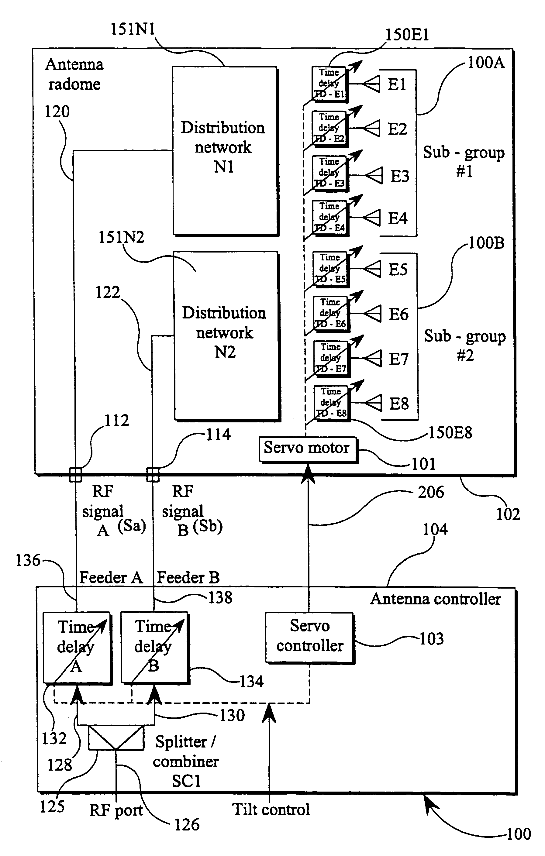
[0037]The systems of the invention as described in the preceding paragraphs provide several advantages over existing systems. In particular, control and / or adjustment of the phases of signals supplied to each sub-array in the antenna assembly can be achieved simply and quickly and from a location remote from the antenna assembly. It is known to adjust the angle of tilt of an antenna by manual mechanical adjustment of the antenna elements and / or the antenna housing mounted on the antenna carrier or mast itself. Such an adjustment process is inconvenient and labour intensive. The present invention provides the advantage that the angle of tilt can be adjusted from a location remote from the antenna mast by electrical means, for example from a base station or control centre at the base of the antenna mast, or a base station situated several kilometers from the mast. Moreover, the system is appropriate for multi-user (i.e. multi operator) applications, by providing each user with independently operable control means, and by combining the user signals in a frequency selective combiner device.
[0038]The invention also provides the advantage that the distribution of the phase and amplitude of the signals fed to each antenna element is controlled so as to provide improved control of the antenna gain and side lobe level, particularly when the system is electrically tilted. The provision of the mechanical phase adjustment means, for example, for further adjusting the phase of signals supplied to each element of the array, provides the user with a means of fine tuning the vertical radiation pattern, to permit further optimisation of the boresight gain and sidelobe levels.
[0039]This aspect of the invention also provides an advantage over other known techniques in that a reduction in the number of components required to adjust the electrical tilt of the antenna assembly may be achieved with a corresponding reduction in system complexity and cost.

Problems solved by technology

A disadvantage of mechanical adjustment of the angle of electrical tilt is that it must be carried out in situ by manual mechanical adjustment of the antenna.

Method used


Image

  • Antenna system
  • Antenna system
  • Antenna system

Examples


Embodiment Construction

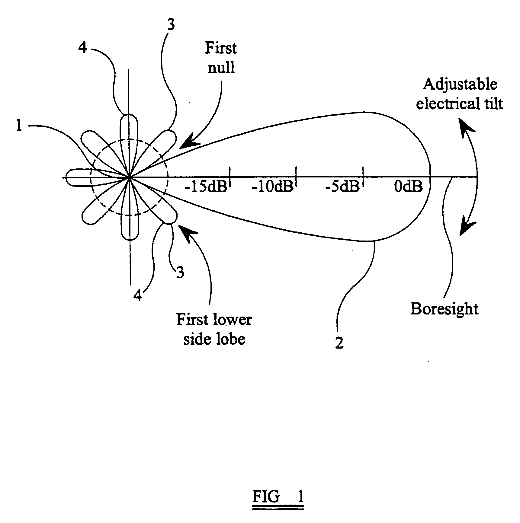
[0056]FIG. 1 shows the vertical radiation pattern (VRP) of a conventional phased array antenna assembly. The drawing is shown in side view and the antenna assembly is represented by the point 1.

[0057]The VRP of the antenna assembly 1 consists of a main lobe or “boresight”2 which diverges in a vertical plane as it extends from the antenna assembly and represents the region of maximum radiation intensity of the beam radiated by the antenna assembly. The VRP of the antenna assembly also includes a number of side lobes 4, representing regions of much lower radiation intensity, which extend from the antenna assembly in directions which are approximately equiangularly spaced about the antenna assembly in a vertical plane. The lobes 3 immediately adjacent the boresight 2 are termed the first upper and first lower side lobes respectively.

[0058]The angle of tilt of the antenna assembly, when adjusted mechanically by physically moving the antenna elements and / or their housing or casing, is kn...


PUM


Abstract

An antenna system for sharing of operation employs contiguous transmit frequencies. Transmit frequencies are separated into non-contiguous sub-groups isolated from one another by filters 158(+) and 160(−) associated with positive and negative polarisation. Received frequencies are filtered and split into five signals for input to base station receive ports. Non-contiguous transmit frequency sub-groups are combined by a quadrature hybrid 110 and pass with 90 degree relative phase shift to mutually orthogonal antenna stack ports P(+) and P(−) associated with orthogonally polarised sets of antenna elements AS(+) and AS(−): the ports P(+) and P(−) are isolated from one another by the hybrid 110. The 90 degree phase shift results in one transmit subgroup being radiated with left hand circular polarisation and the other transmit subgroup being radiated with right hand circular polarisation. Changing the relative phase shift changes the radiated polarisation to linear or elliptical, and signal amplitude weighting provides control of antenna beam polarisation direction.

Description

BACKGROUND OF THE INVENTION[0001](1) Field of the Invention[0002]The present invention relates to an antenna system and particularly, but not exclusively, to a phased array antenna system having a plurality of antenna elements arranged in at least two sub-arrays. The antenna system is suitable for use in many telecommunications systems but finds particular application in cellular mobile radio networks, commonly referred to as mobile telephone networks. More specifically, the antenna system of the present invention may be used with third generation (3G) mobile telephone networks and the Universal Mobile Telephone System (UMTS).[0003](2) Description of the Art[0004]Operators of cellular mobile radio networks generally employ their own base-stations, each of which includes one or more antennas. In a cellular mobile radio network, the antennas are a factor in defining the desired coverage area which is generally divided into a number of overlapping cells, each associated with a respecti...

Claims


Application Information

Patent Timeline
IPC IPC(8): H01Q3/00H01Q1/50H01Q1/24H01Q3/32H01Q3/34H01Q3/36H01Q21/00H01Q21/06
CPCH01P1/184H01Q1/246H01Q3/32H01Q3/36H01Q21/0006
Inventor THOMAS, LOUIS DAVIDHASKELL, PHILIP EDWARDWYNN, DUNCAN ALAN
Owner QUINTEL CAYMAN LTD
Learn More