Method of motion correction in optical coherence tomography imaging

Active Publication Date: 2008-04-29
CARL ZEISS MEDITEC INC
View PDF17 Cites 105 Cited by
  • Summary
  • Abstract
  • Description
  • Claims
  • Application Information

AI Technical Summary

Problems solved by technology

There is also motion along the OCT beam, which is not detectable by the common designs of eye trackers, but which does distort the OCT image.

Method used


Image

  • Method of motion correction in optical coherence tomography imaging
  • Method of motion correction in optical coherence tomography imaging
  • Method of motion correction in optical coherence tomography imaging

Examples


Embodiment Construction

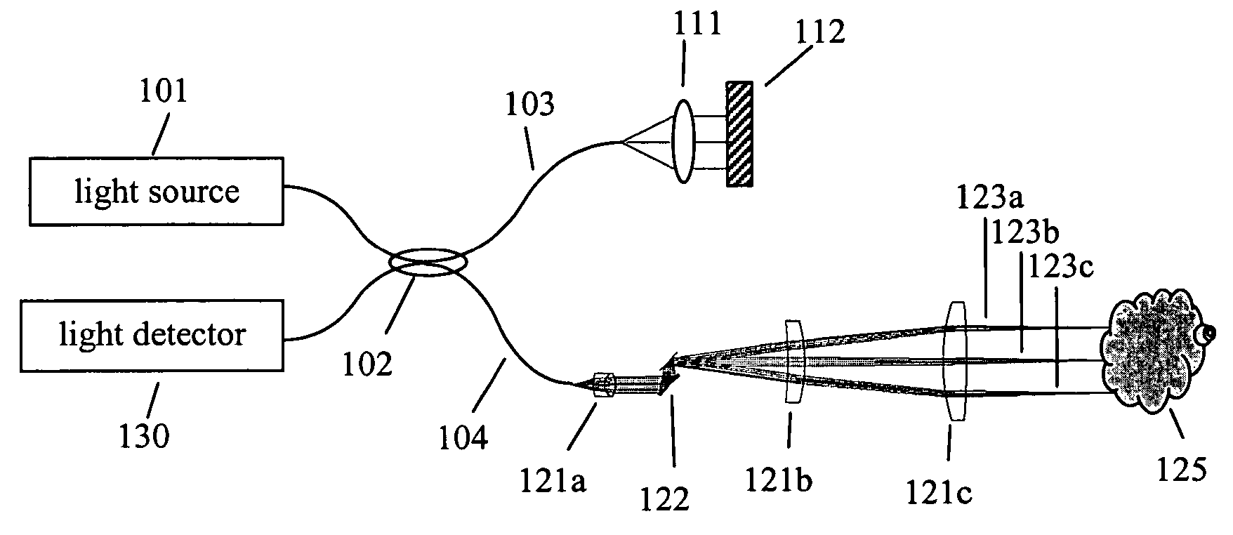
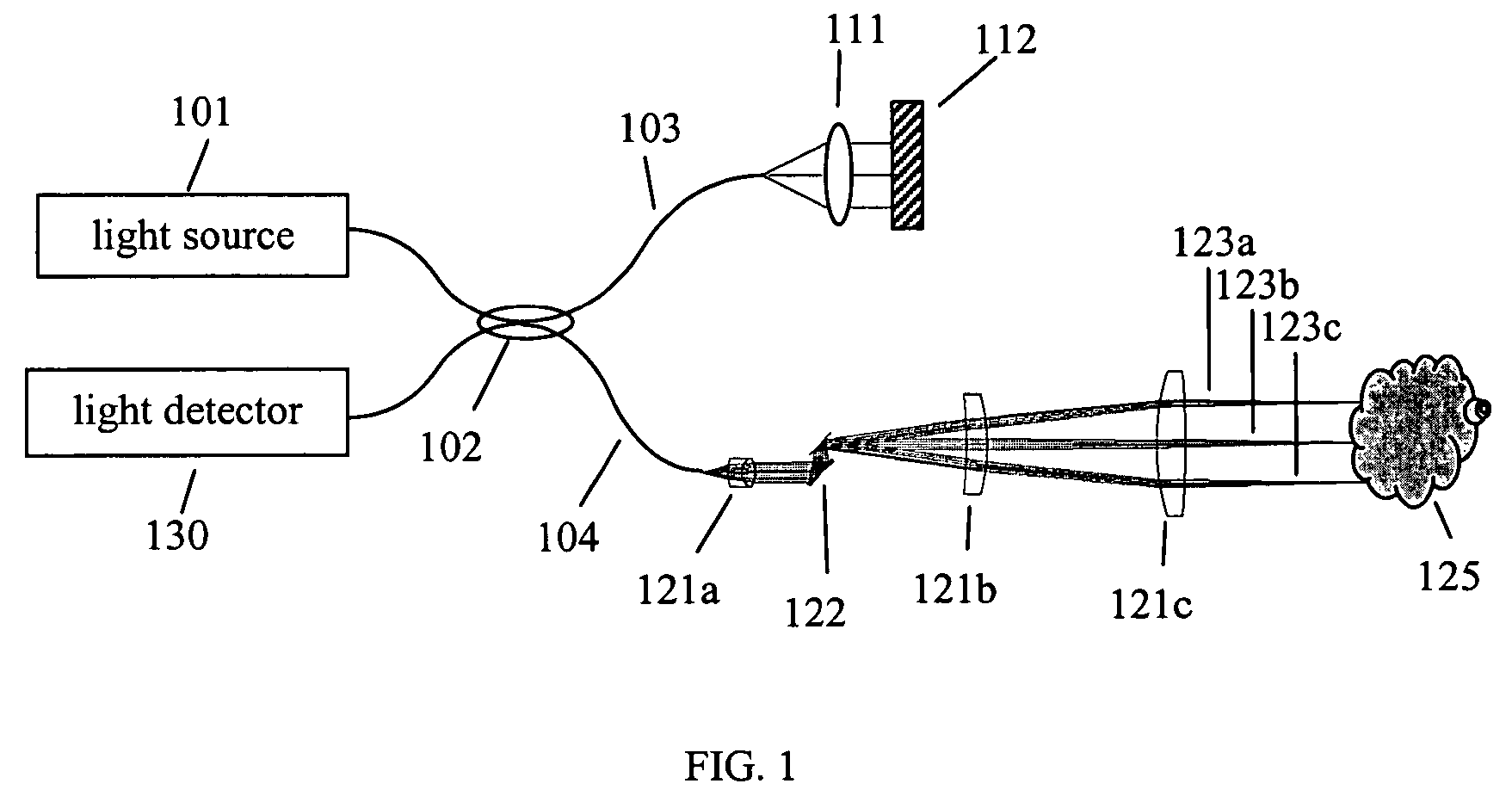
[0016]FIG. 1 is a schematic illustration of one design of OCT system. The light source 101 provides light having a short-coherence length to the fiber-based interferometer. Directional coupler 102 serves to split the light from source 101 between a reference arm 103 and a sample arm 104. Lens 111 and mirror 112 serve to return reference light back to coupler 102. A scanning system including lenses 121a, 121b, and 121c, and scanning mirrors 122, directs light successively along paths such as 123a, 123b, 123c onto successive locations on sample 125. Some light scattered from sample 125 returns closely enough along the illumination path to re-enter the fiber interferometer, is combined with reference light in coupler 102. The interfered sample and reference light are detected in detector 130.

[0017]The scanning mirror 122 is controlled by a system processor and generates scan coordinates which correspond to certain transverse positions on the sample. A sample, such as the human eye, wil...


PUM


Abstract

An image data set acquired by an optical coherence tomography (OCT) system is corrected for effects due to motion of the sample. A first set of A-scans is acquired within a time short enough to avoid any significant motion of the sample. A second more extensive set of A-scans is acquired over an overlapping region on the sample. Significant sample motion may occur during acquisition of the second set. A-scans from the first set are matched with A-scans from the second set, based on similarity between the longitudinal optical scattering profiles they contain. Such matched pairs of A-scans are likely to correspond to the same region in the sample. Comparison of the OCT scanner coordinates that produced each A-scan in a matching pair, in conjunction with any shift in the longitudinal scattering profiles between the pair of A-scans, reveals the displacement of the sample between acquisition of the first and second A-scans in the pair. Estimates of the sample displacement are used to correct the transverse and longitudinal coordinates of the A-scans in the second set, to form a motion-corrected OCT data set.

Description

PRIORITY[0001]This application claims the benefit of the filing date under 35 U.S.C. § 119(e) of U.S. Provisional Patent Application Ser. No. 60 / 645,637, filed Jan. 21, 2005, which is hereby incorporated by reference in its entirety.TECHNICAL FIELD OF THE INVENTION[0002]The present invention relates to data acquisition methods for imaging by optical coherence tomography (OCT). In particular, the invention is a method for determining patient motion occurring during the acquisition of large sets of data by OCT. The method described herein acquires a sparse set of OCT data in a sufficiently short time that patient motion during the acquisition is not objectionable. The sparse set of OCT data acts as a set of guideposts for determination of the locations on the sample, of the measurements comprising the full data set.BACKGROUND OF THE INVENTION[0003]Optical Coherence Tomography (OCT) is a technique for performing high-resolution cross-sectional imaging that can provide images of tissue ...

Claims


Application Information

Patent Timeline
Patent Type & Authority Patents(United States)
IPC IPC(8): G01B9/02G01B11/02G01B9/10G01J4/00
CPCA61B3/102A61B3/1233A61B5/0059A61B5/0066G01N21/4795G01B9/02048G01B9/02077G01B9/02087A61B3/113G01B9/02091G01N2021/1787A61B3/0025
Inventor EVERETT, MATTHEW J.O'HARA, KEITH E.
Owner CARL ZEISS MEDITEC INC
Why Eureka
Try Eureka