Laser apparatus and method for assembling the laser apparatus

a laser and laser beam technology, applied in the field of laser beams, can solve the problems of reducing the input efficiency of laser beams which are condensed by the condensing lens and enter the optical fiber, and similar problems can occur

Active Publication Date: 2008-05-06
ADTEC ENG +1
View PDF4 Cites 8 Cited by
  • Summary
  • Abstract
  • Description
  • Claims
  • Application Information

AI Technical Summary

Benefits of technology

[0028](III) The first and second aspects of the present invention have the following advantages.
[0029](1) The method according to the second aspect of the present invention enables adhesive fixing of the attachment part to the fixing member in such a manner that the adhesion surface of the attachment part is precisely parallel to the mounting surfaces of the fixing member. For example, in the case where the first reference surface and the mounting surface of the fixing member are arranged in parallel, and the second reference surface and the adhesion surface of the attachment part are arranged in parallel, the adhesion surface of the attachment part is parallel to the mounting surface of the fixing member when the second angle (which the second reference surface of the attachment part makes with the predetermined reference direction) is equal to the first angle (which the first reference surface makes with the predetermined reference direction). Therefore, it is possible to fix the attachment part to the fixing member in such a manner that the adhesion surface of the attachment part is parallel to the mounting surface of the fixing member, for example, by adhering the adhesion surface of the attachment part to the mounting surface of the fixing member with spots of adhesive while the second angle is equal to the first angle.
[0030]In addition, when the above first and second angles are measured by using a laser autocollimator, the precision in the measurement becomes very high. Therefore, it is possible to make the adhesion surface of the attachment part and the mounting surface of the fixing member precisely parallel with each other.
[0032](3) In order to precisely measure the second angle (which the second reference surface of the attachment part makes with the predetermined reference direction) and the first angle (which the first reference surface of the fixing member makes with the predetermined reference direction), it is desirable to use an optical technique in which a laser beam is reflected by each of the first and second reference surfaces. For example, it is desirable to use the aforementioned laser autocollimator. In the case where the first reference surface and the second reference surface have an arithmetic average roughness (Ra) smaller than 0.08 micrometers, it is possible to suppress scattering of the laser beam by the first reference surface and the second reference surface, so that it is possible to realize highly satisfactory measurement of the first and second angles by using the above optical technique.
[0033](4) Further, in the case where the surface which is adhesively fixed to the first reference surface of the fixing member or the second reference surface of the attachment part (each having an arithmetic average roughness (Ra) smaller than 0.08 micrometers) has an arithmetic average roughness (Ra) equal to or greater than 0.15 micrometers and smaller than 0.35 micrometers, i.e., in the case where the surface adhesively fixed to the first reference surface or the second reference surface is relatively rough, penetration of an adhesive into the gap between the above surface and the first reference surface or the second reference surface is facilitated, so that it is possible to realize satisfactorily effective adhesion.
[0034](5) Furthermore, in the case where the laser apparatus according to the first aspect of the present invention comprises a single optical fiber, one or more laser sources which emit a plurality of laser beams, and an optical system which makes the plurality of laser beams enter the optical fiber through an end face of the optical fiber, it is possible to coaxially align the optical axis of the optical system and the core axis of the optical fiber with high precision, so that sufficiently high input efficiency of the laser beams into the optical fiber is ensured.

Problems solved by technology

Although the inclination of the condensing lens fixed in the above manner is slight, the slight inclination of the condensing lens causes misalignment between the optical axis of the condensing lens and the core axis of the near-end portion of the optical fiber, so that the input efficiency of the laser beams which is condensed by the condensing lens and enters the optical fiber is reduced.
In the above examples, the problems arise in the laser apparatuses in which a plurality of laser beams enter a single optical fiber and are optically combined.
However, even in other laser apparatuses, similar problems can also occur, i.e., an adhesion surface of an optical component such as a lens or a holder for fixing an optical component can be fixed to a mounting surface of a member arranged on the main body side of each laser apparatus with an inclination from the mounting surface.

Method used


Image

  • Laser apparatus and method for assembling the laser apparatus
  • Laser apparatus and method for assembling the laser apparatus
  • Laser apparatus and method for assembling the laser apparatus

Examples


Embodiment Construction

[0042]An embodiment of the present invention is explained in detail below with reference to drawings.

Construction

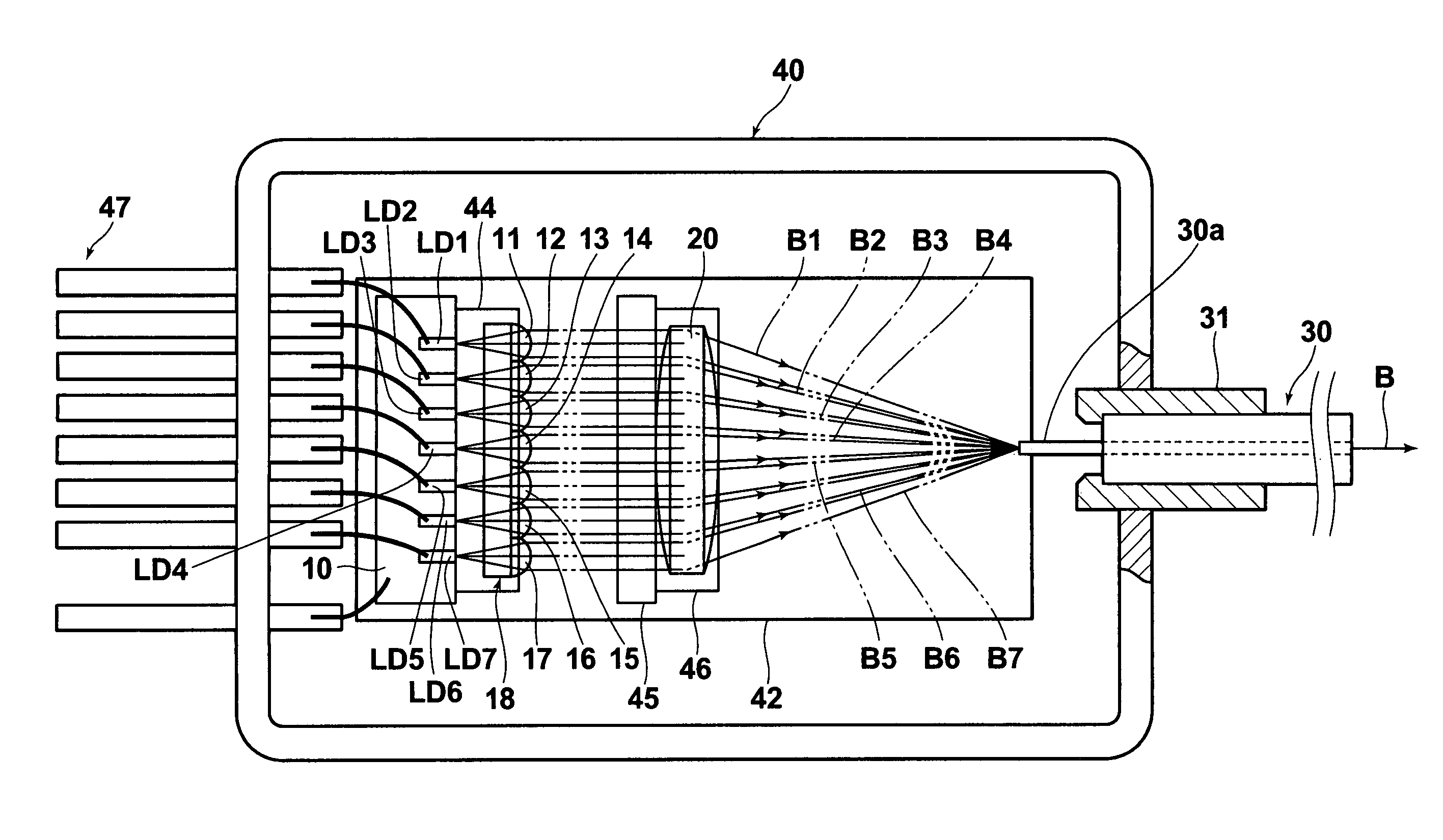
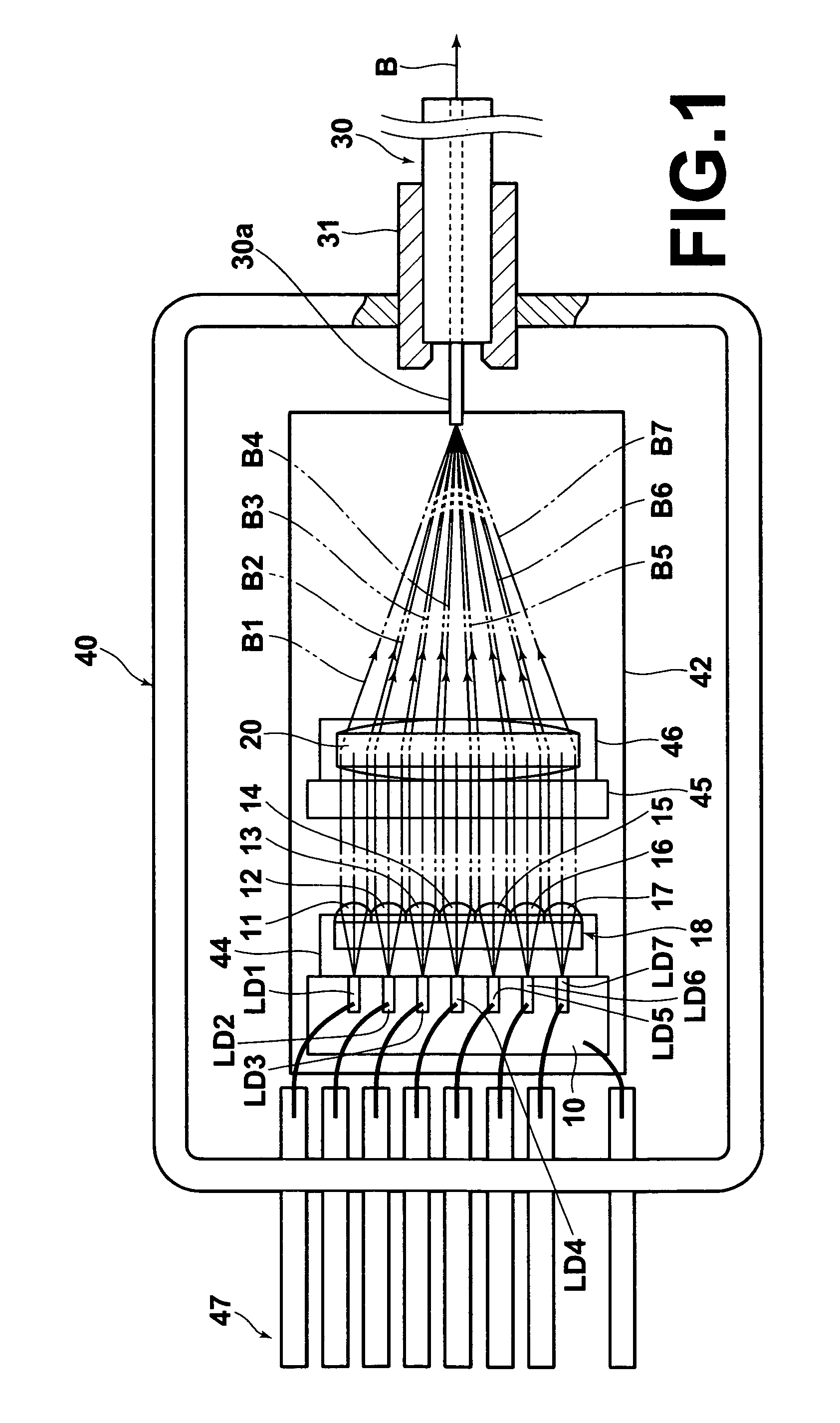
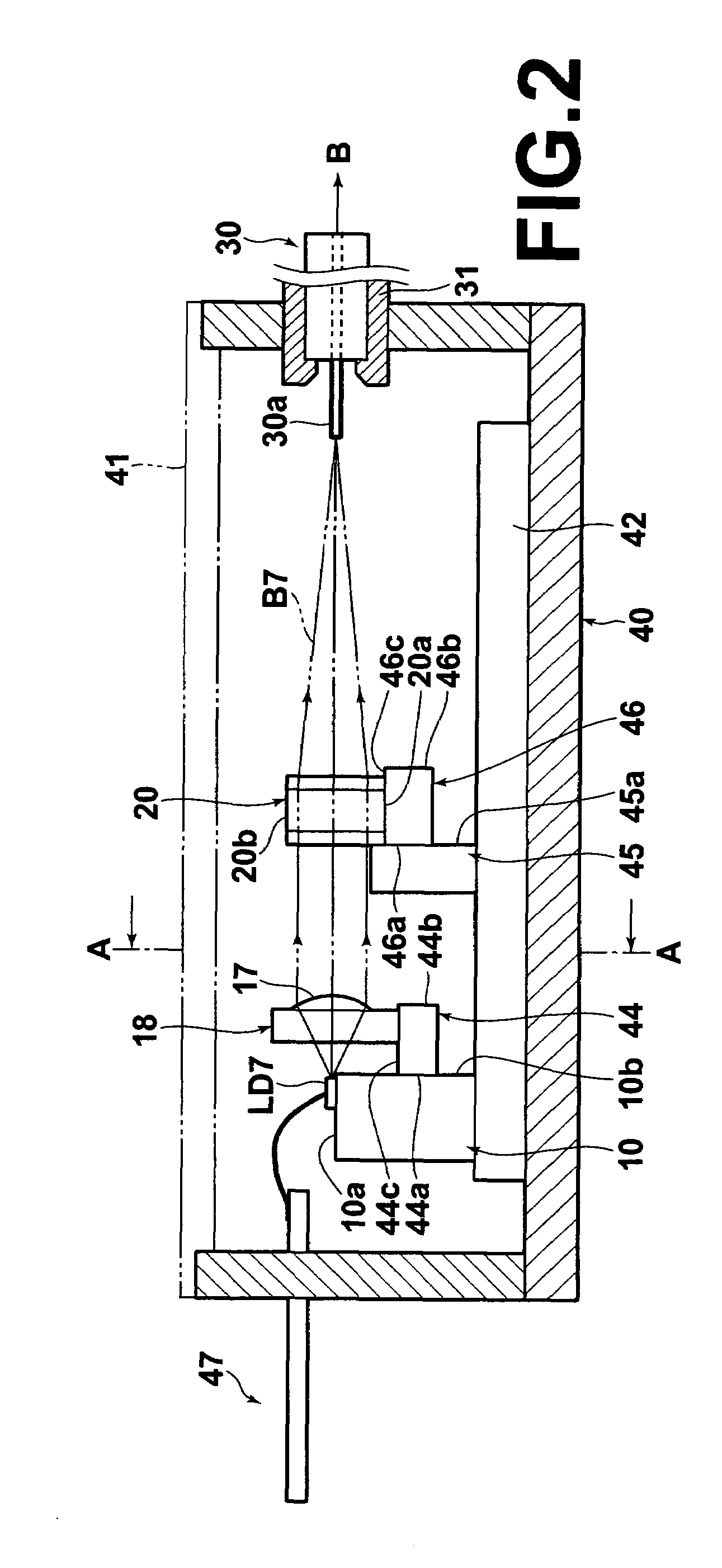
[0043]FIGS. 1 and 2 are respectively plan and side views, partly in cross section, of a laser apparatus according to an embodiment of the present invention, and FIG. 3 is a front view of a rear half of the laser apparatus which is cut at the cross section A-A indicated in FIG. 2. The laser apparatus according to the present embodiment is a high-luminosity combined-ultraviolet-light laser apparatus (which may be hereinafter referred to as a combined laser apparatus or a laser-light source).

[0044]As illustrated in FIGS. 1, 2, and 3, the laser apparatus according to the present embodiment comprises a plurality (e.g., seven) of GaN-based semiconductor laser chips LD1, LD2, LD3, LD4, LD5, LD6, and LD7, a collimator-lens array 18, a condensing lens 20, and a multimode optical fiber 30. The GaN-based semiconductor lasers LD1 through LD7 are arrayed on and fixed to a heat block 1...


PUM


Abstract

In a laser apparatus: an adhesion surface and a first reference surface making a first predetermined angle with the adhesion surface are formed on an attachment part, and a mounting surface and a second reference surface making a second predetermined angle with the mounting surface are formed on a fixing member which is directly or indirectly fixed to a main body and arranged to adhesively hold the attachment part. In a method for assembling the laser apparatus: a first angle between the second reference surface and a reference direction is measured; the orientation of the attachment part is adjusted while measuring a second angle between the first reference surface and the reference direction; and the attachment part is adhesively fixed to the fixing member when the second angle is equal to an angle predetermined based on the first angle and the first and second predetermined angles.

Description

BACKGROUND OF THE INVENTION[0001]1. Field of the Invention[0002]The present invention relates to a laser apparatus in which one or more optical components (including, for example, a condensing lens) and one or more holders for the one or more optical components are directly or indirectly fixed to a main body by adhesion. The present invention also relates to a method for assembling the above laser apparatus.[0003]2. Description of the Related Art[0004]Some known types of laser apparatuses optically combine a plurality of laser beams in a single optical fiber, and output a high-power laser beam by inputting the plurality of laser beams into the single optical fiber. For example, such laser apparatuses are disclosed in U.S. Pat. No. 6,995,912 and Japanese Unexamined Patent Publication No. 2004-134641. The disclosed laser apparatuses are basically constituted by one or more semiconductor lasers which emit a plurality of laser beams, a single optical fiber, and an optical condensing sys...

Claims


Application Information

Patent Timeline
Patent Type & Authority Patents(United States)
IPC IPC(8): G02B6/36
CPCG02B6/4206
Inventor NAGANO, KAZUHIKOTERAMURA, YUICHI
Owner ADTEC ENG
Why Eureka
Try Eureka