

Electrical connector with shortened contact and crosstalk compensation
a technology of crosstalk compensation and electrical connectors, applied in the direction of coupling devices, two-part coupling devices, electrical apparatus, etc., can solve the problem that the split pair will suffer a significant near-end crosstalk (next) problem, and achieve high throughput.
- Summary
- Abstract
- Description
- Claims
- Application Information
AI Technical Summary
Benefits of technology
Problems solved by technology
Method used
Image

Examples
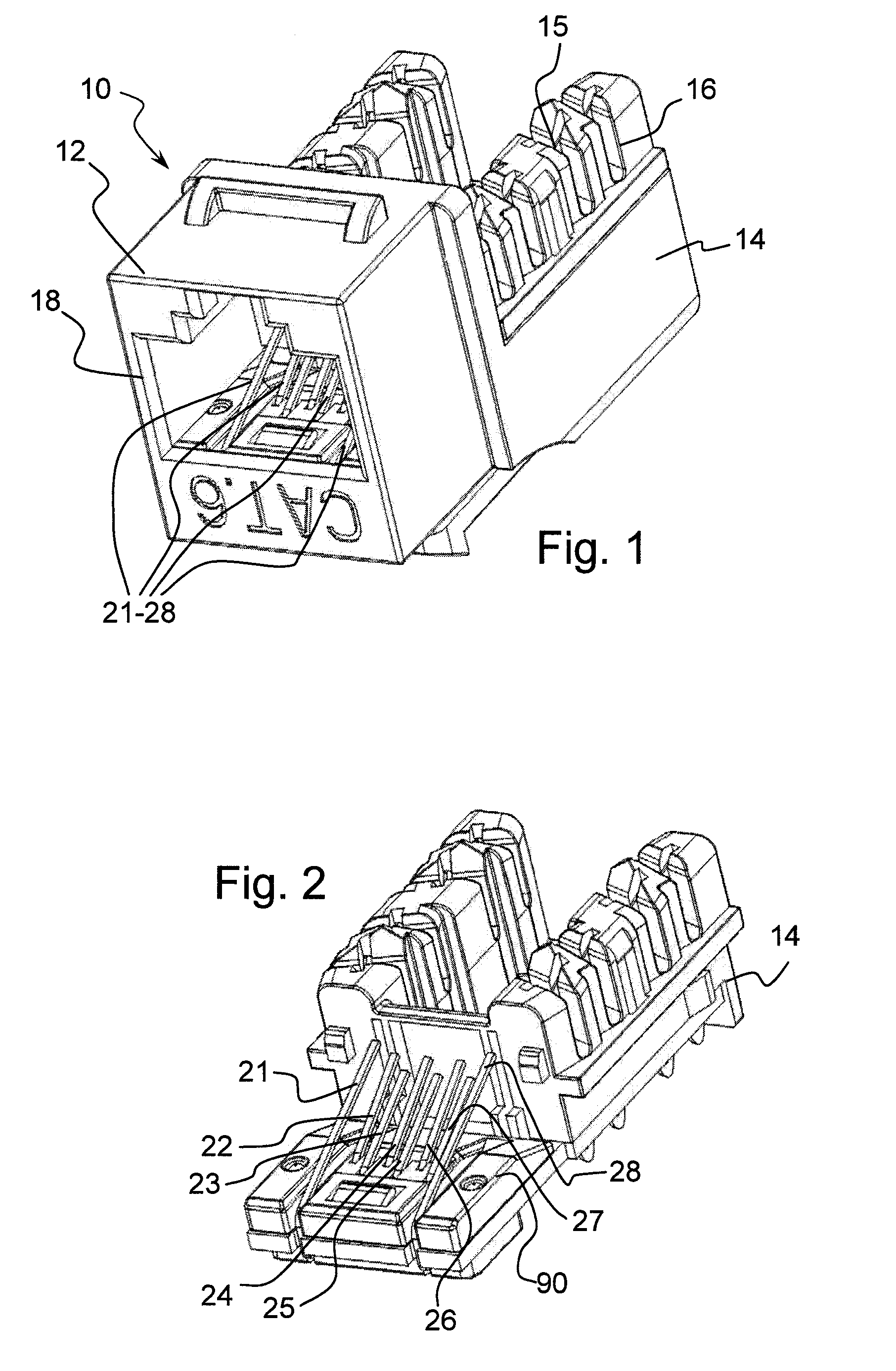
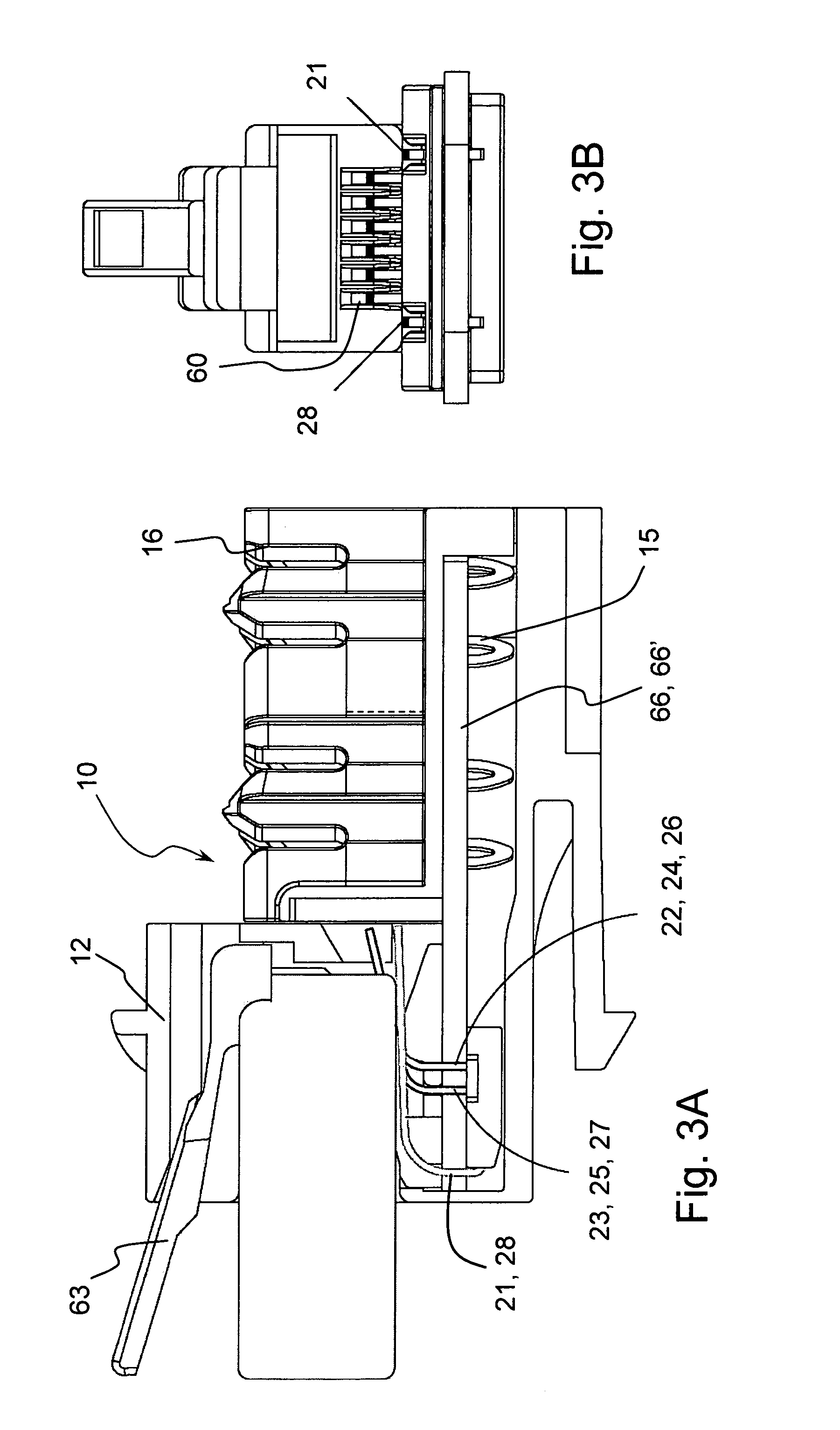
first embodiment
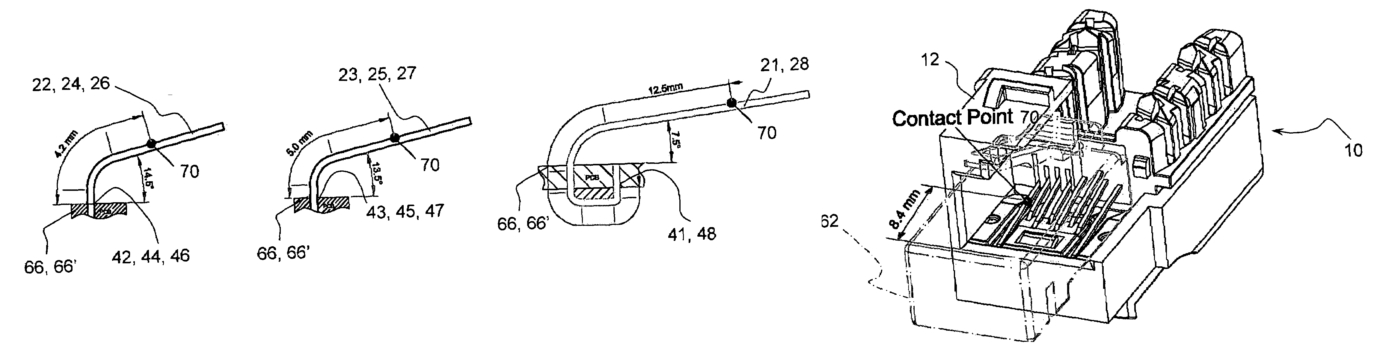
[0045]the invention limits the compensation to a single compensation signal (single compensating element) such that φ should not be more than 3.8 degrees. Otherwise, the resulting NEXT noise will not be acceptable (CAT 6 performance will not be attained). Applicant has also noticed that if the manufacturing tolerance is more than 14%, there is no apparent way to use a single compensation signal to reach the CAT6 performance requirements.
[0046]When considering the electromagnetic waves propagated in the transmission line made of copper, one can use a usual speed factor of 0.65. The wavelength at 250 MHz will be 0.78 meter. As such the physical length related to a 3.8 degree phase delay is 8.2 mm. However, because the compensation signal takes a round way trip in the transmission line (using first signal path and second signal path of a transmission line), the real distance between v1 and v2 (between the contact region and the compensation element connection region) is usually less th...
second embodiment
[0059]Another embodiment of the invention is described with reference to FIGS. 10 through 12. This connector 10 has a circuit board 66′ that uses more than one compensation element for at least some of the paths (multi-phase compensation). Connector 10 presents hardware for 10 G performance through 500 MHz. To design a connector for high frequency and high performance, a well-known crosstalk compensation scheme called multi-phase compensation can be used, providing a compensation phase between the same lines, in addition to the first phase, the technique discussed above. But, if the frequency band is too wide (so as to provide high throughput-bandwidth), the time delay of the compensation will make it difficult to balance the performances at both ends of the frequency band. The techniques as to spring contact length and termination relative to the contact zone 70 is also used for the first phase in the second embodiment for 10 G performance and at least one second phase is also prov...
PUM
 Abstract
Description
Claims
Application Information