Method for controlling plasma density or the distribution thereof

a plasma density and distribution technology, applied in the direction of vacuum evaporation coatings, electrolysis components, coatings, etc., can solve the problems of hardly possible variation of this distribution or the geometry of the permanent magnetic configuration

Inactive Publication Date: 2008-05-06
OERLIKON ADVANCED TECH +1
View PDF18 Cites 19 Cited by
  • Summary
  • Abstract
  • Description
  • Claims
  • Application Information

AI Technical Summary

Problems solved by technology

Apart from fundamentally the great advantages of magnetron sources, this increasingly developing erosion trench, has negative effects onCoating homogeneity on the coated substrate,Degree of utilization of the target material.
If it is taken into consideration that the looped magnetic field circulating in the form of a tunnel is conventionally realized by a configuration of strong permanent magnets beneath the target configuration, it is evident that, on the one hand, an existent permanent magnet configuration which, for shifting said magnetic field, is mechanically moved beneath the target configuration, can only be geometrically changed with relatively high expenditures, in order to realize different erosion profile distributions, and that in sputter operation a variation of this distribution or of the geometry of the permanent magnetic configuration is hardly possible.

Method used


Image

  • Method for controlling plasma density or the distribution thereof
  • Method for controlling plasma density or the distribution thereof
  • Method for controlling plasma density or the distribution thereof

Examples


Embodiment Construction

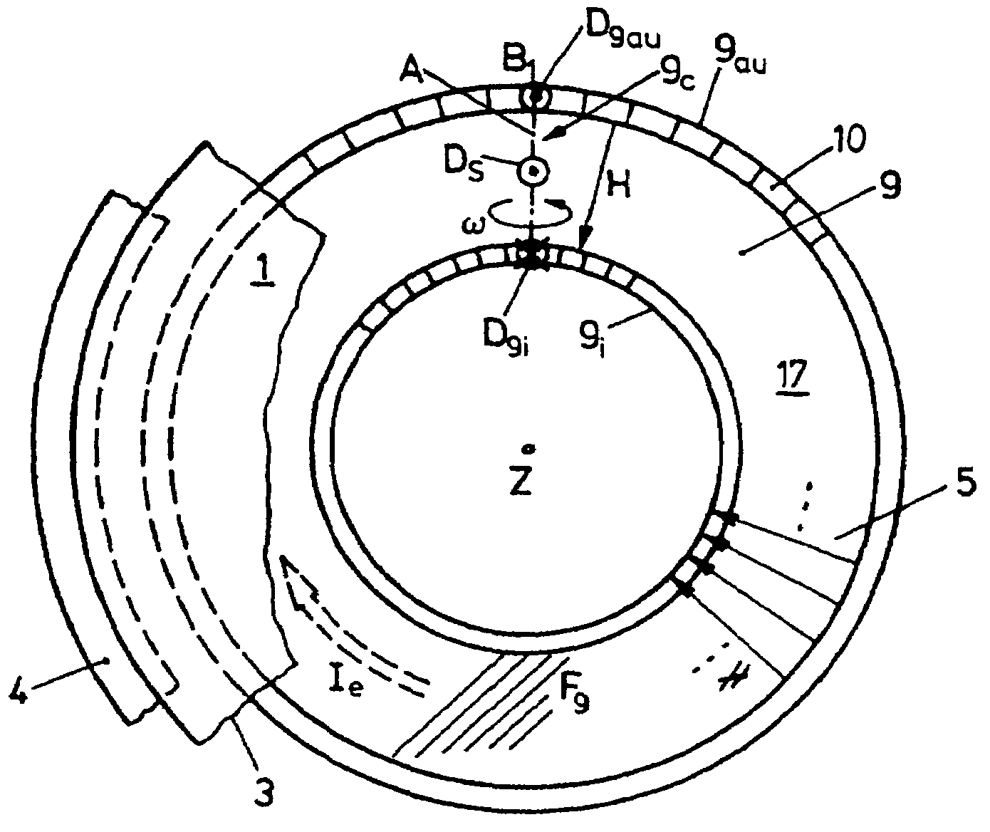
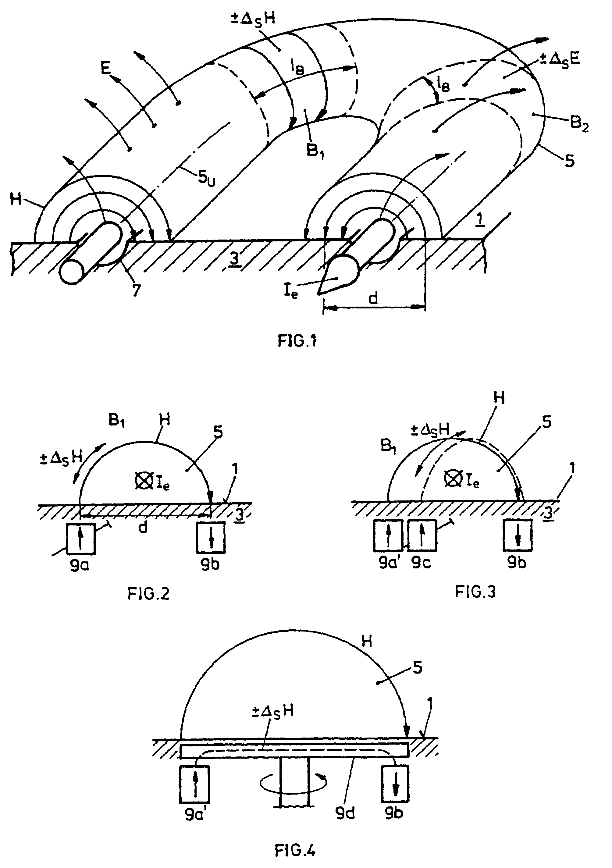
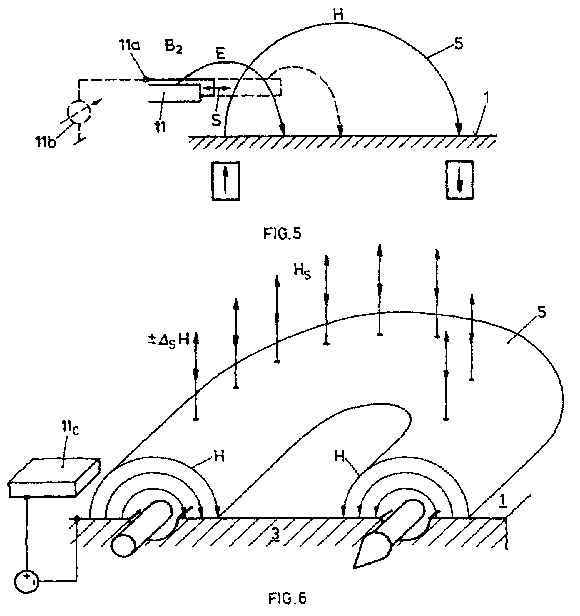
[0058]In FIG. 1, schematically and without claiming scientific exactness, the conditions are depicted in the case of realization of the invention under its first formulation. Over the sputter surface 1 of a target configuration 3, in a manner not further shown here, for example with two collars of permanent magnets disposed beneath the target configuration 3, a tunnel-form magnetic field H is generated, which circulates in a closed loop 5 over the sputter surface 1.

[0059]In the zone of the loop 5 further an electric field E intersecting the magnetic field H at an angle is built-up between the target configuration as the cathode and a discharge anode (not shown) provided in known manner. Based on these field conditions, an efficient electron trap develops, which produces a well-known electron current Ie, which substantially circulates in the magnetic field loop 5 and is substantially greater than the plasma discharge current away from said tunnel-form field. Based on the high electro...


PUM

PropertyMeasurementUnit
pressuresaaaaaaaaaa
lengthaaaaaaaaaa
magnetic fieldaaaaaaaaaa

Abstract

Method for manufacturing magnetron sputter-coated workpieces includes placing a substrate adjacent a magnetron source having a target cathode, generating above the target cathode, at least one plasma loop by an electron trap established by generating a magnetic field which forms, in top view on the target cathode, a magnet field loop and, viewed in cross-section on the target cathode, a tunnel-shaped arc field and, an electric field which crosses the magnetic field of the magnet field loop. Plasma density distribution above the target cathode is controlled by interacting a control anode with the electron trap in a control segment area of the plasma loop. Magnetron sputter-coating the substrate by the magnetron sputter-source then takes place.

Description

CROSS-REFERENCE TO RELATED APPLICATION[0001]This is a divisional of U.S. patent application Ser. No. 10 / 225,717, filed Aug. 22, 2002 and now U.S. Pat. No. 6,821,397, which was a continuation of PCT / CH01 / 00021 filed Jan. 12, 2001, and claimed priority on Swiss application CH 351 / 00 filed Feb. 23, 2000, which priority is repeated here.FIELD AND BACKGROUND OF THE INVENTION[0002]The present invention relates to a method for controlling plasma density or its distribution over the target configuration of a magnetron source, a method for the production of coated workpieces, as well as magnetron sources.Definition[0003]By magnetron source is understood a sputter source, on which the discharge is operated with DC, AC or mixed AC and DC, or with pulsed DC, wherein AC is to be understood as extending up into the HF range. The source is conventionally operated under vacuum with a working gas, such as for example argon, at pressures of a few mbar up to 10−3 mbar. In known manner, reactive additi...

Claims


Application Information

Patent Timeline
Patent Type & Authority Patents(United States)
IPC IPC(8): C23C14/35H01J37/34
CPCH01J37/3408
Inventor KRASSNITZER, SIEGFRIED
Owner OERLIKON ADVANCED TECH
Why Eureka
Try Eureka