Method for testing a superconductor under increased current load in a series-produced and actively shielded superconducting NMR magnet

a superconducting nmr magnet and increased current technology, which is applied in the direction of superconducting magnets/coils, geological measurements, and using reradiation, etc., can solve the problems of unacceptably large, high cost, and high cost of magnet windings required to achieve the required field, so as to facilitate the setting of the current in the superconductor to be tested and facilitate the effect of magnet coil configuration

Active Publication Date: 2008-05-06
BRUKER BIOSPIN
View PDF10 Cites 4 Cited by
  • Summary
  • Abstract
  • Description
  • Claims
  • Application Information

AI Technical Summary

Benefits of technology

[0015]The central idea of the invention is to subdivide the magnet coil configuration into at least one first and one second partial region. A superconducting wire is wound in the first partial region whose NMR capability shall be tested under increased current load compared to the operating current of the standard magnet. With the inventive method, a non-vanishing current difference of ΔI(2)-ΔI(1) is obtained between the two partial regions after the charging process, which permits setting of a higher current load in the superconductor of the first partial region to be tested, and at the same time does not subject the standard superconductors in the second partial region of the magnet coil configuration to a higher current than in the standard series-produced magnet. After performance of the inventive method, the temporal field stability of the magnet coil configuration can be tested by measuring the NMR signal. After successful testing of the superconductor, the magnet coil configuration may be charged to the standard current at the customer's location, thereby obtaining the specified magnetic field with open additional switch and without excess current in the first partial region which can be superconductingly short-circuited, since the superconductor to be tested has the same dimensions as the standard superconductor which it replaces. The tested superconductor may remain in the magnet after the test, and the magnet can be installed at the customer's location without taking additional measures. If the superconductor loaded with an increased current in the first partial region does not pass the test, i.e. the magnet coil configuration does not meet the desired drift criterion, the magnet may still be delivered as long as the standard current of the magnet coil configuration in the superconductor to be tested does not produce an increased drift. Only one single power supply is required for charging the overall magnet coil configuration in performing the test in accordance with the invention, which saves cost.
[0027]In one particularly preferred variant of the inventive method, the magnet coil configuration comprises at least one further third partial region in addition to the first and second partial regions, which can be separately superconductingly short-circuited using an additional switch. The third partial region renders the magnet coil configuration more flexible. The additional partial region may e.g. be used to test a further superconducting wire of a different conductor type in the magnet coil configuration. A superconductor of Nb3Sn material may e.g. be tested in the first partial region and a superconductor of NbTi may be tested in the new partial region, or the field homogeneity in the center of the magnet coil configuration at the location of the NMR sample can be improved by the third partial region.

Problems solved by technology

One essential problem in the construction of a superconducting NMR (nuclear magnetic resonance) magnet with maximum temporal field stability is the proper loading of the superconducting wire in the magnet.
However, the current must not be excessive, since otherwise the resistance of the superconductor, which cannot be completely eliminated in an actual superconductor, and the associated current reduction in the magnet, i.e. the magnetic field drift, would become excessive.
If the magnet current is excessively low, the number of magnet windings required to achieve the required field would be excessively high, making it unacceptably large and expensive.
Maximum resolution voltage measurement over the entire conductor length wound on the coil body is also not possible.
In this case, the conductor could be tested under NMR conditions, however, with two decisive limitations.
First, the conductor dimension (conductor cross-section) of the series-produced magnet is used, which means that the new conductor type cannot bear a higher load than the standard conductor from the series-produced magnet.
Secondly, if the conductor cross-section of the new conductor type is smaller, the conductor can carry a higher current density, however, the construction of the coil body of the series-produced magnet must be completely changed and adjusted to the new conductor dimension which would involve high constructive effort and expense.
If the conductor does not meet the expectations and would be excessively loaded in the series-produced magnet, this magnet could not be delivered.

Method used


Image

  • Method for testing a superconductor under increased current load in a series-produced and actively shielded superconducting NMR magnet
  • Method for testing a superconductor under increased current load in a series-produced and actively shielded superconducting NMR magnet
  • Method for testing a superconductor under increased current load in a series-produced and actively shielded superconducting NMR magnet

Examples


Embodiment Construction

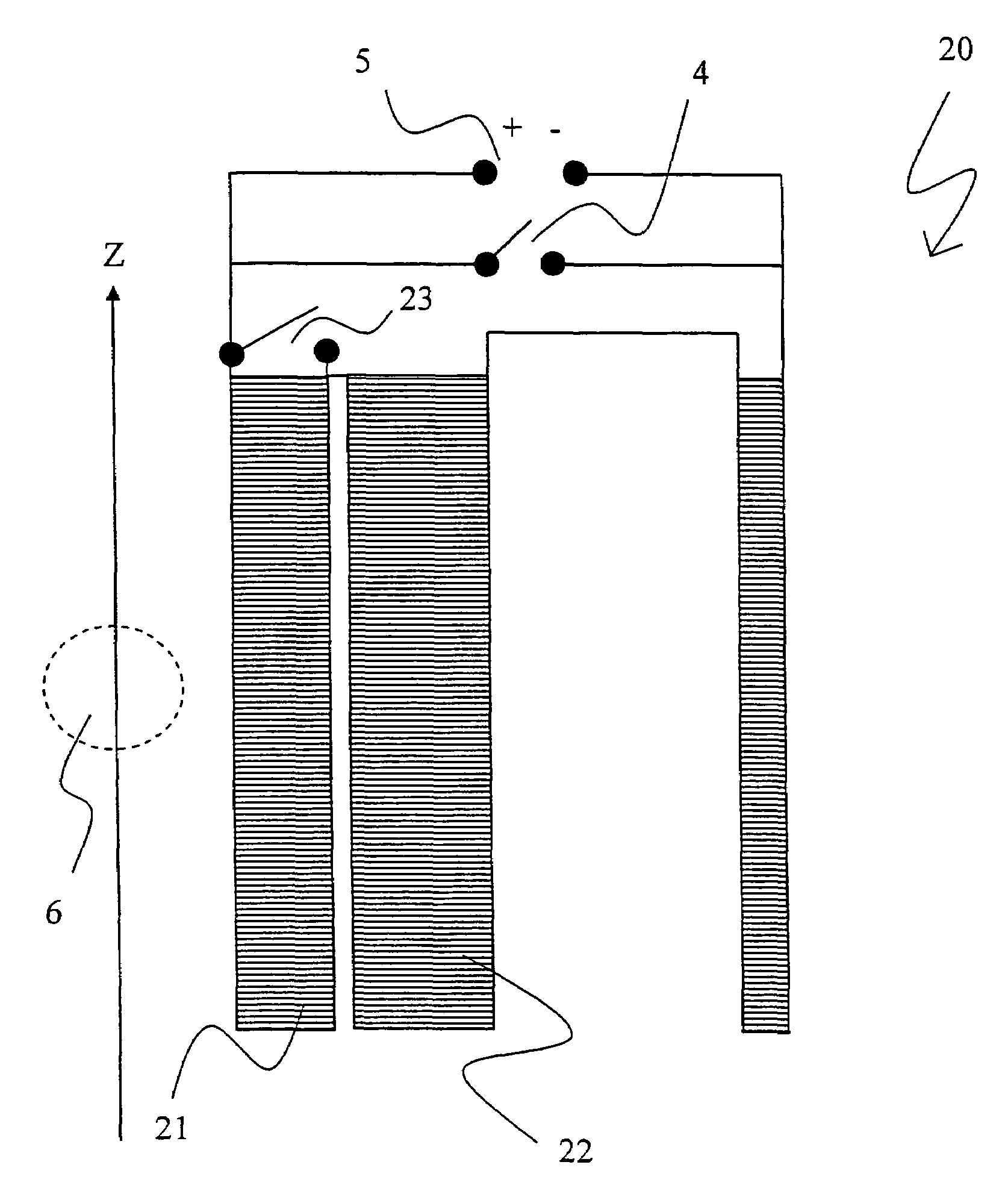
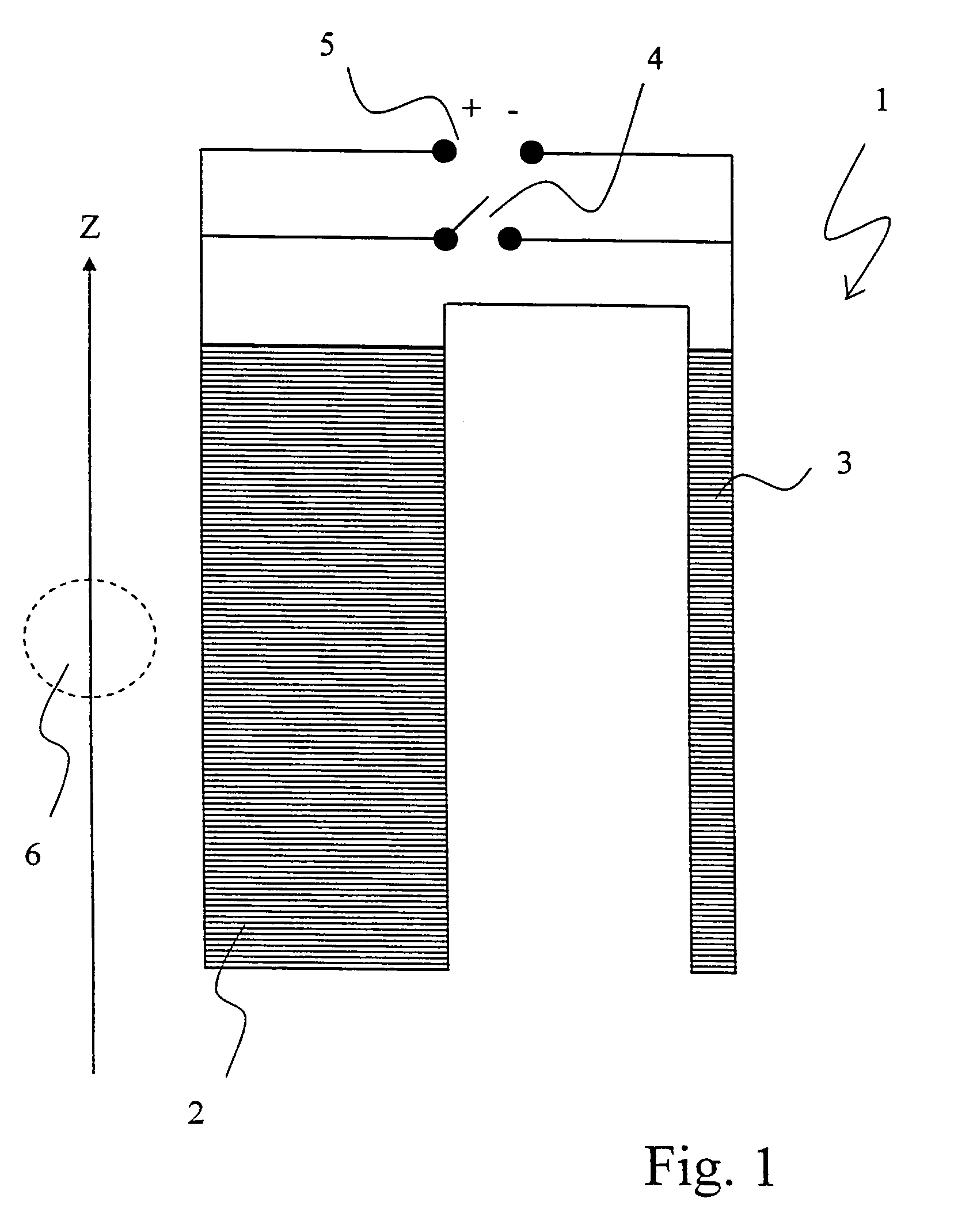
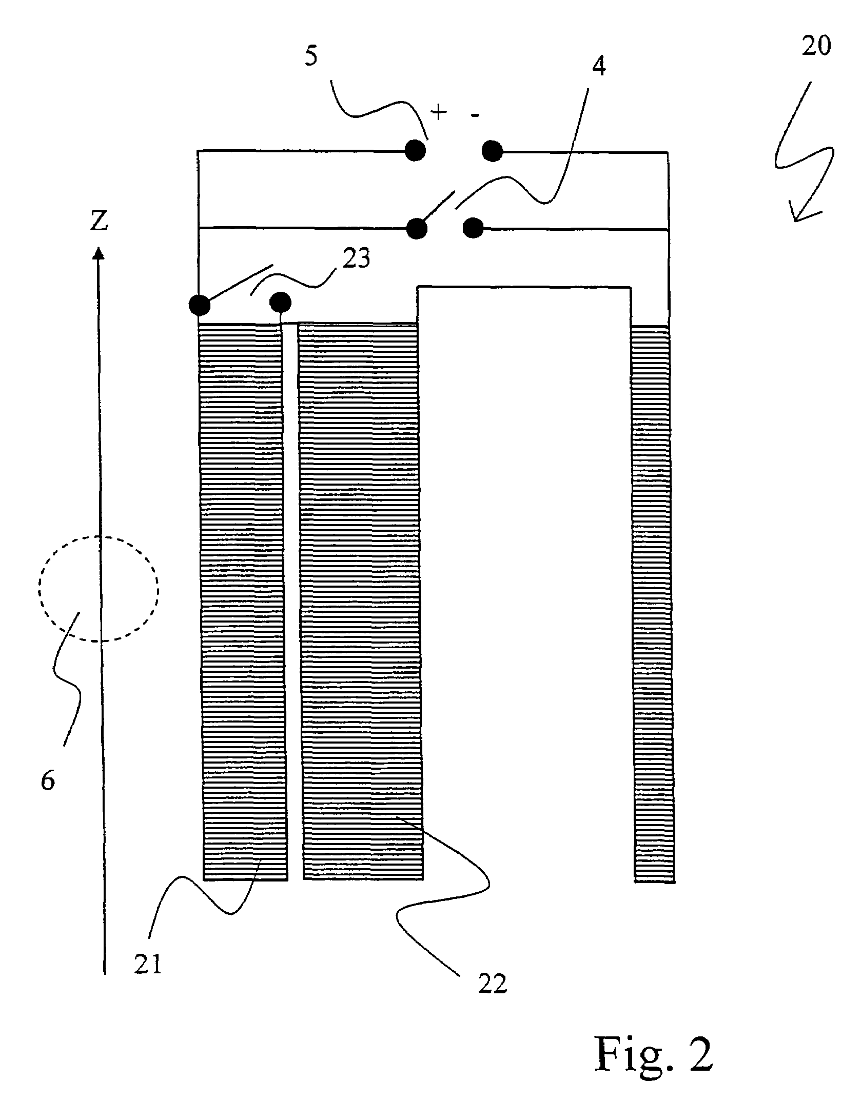
[0031]NMR (nuclear magnetic resonance) spectroscopy methods must meet extremely high demands with regard to the temporal stability of the measured resonance frequency and therefore the temporal stability of the magnetic field of the superconducting magnet coil configuration having the sample to be investigated in its center, whose resonance frequency is proportional to the magnetic field. The specified temporal frequency stability for a 18.9 Tesla magnet with a resonance frequency for hydrogen nuclei of 800 MHz is e.g. 8 Hz / h.

[0032]In order to obtain this stability, the coils of these NMR magnets must be wound with superconducting wire and be operated in the short-circuit mode (“persistent mode”). In order to guarantee this high temporal stability, the superconducting wires (superconductors) in the magnetic field of the magnet coil configuration may not be excessively loaded. The magnet current for the magnetic field in which the superconductor is operating, must not be excessively ...


PUM


Abstract

A method for testing a new superconducting wire involves charging an actively shielded magnet coil configuration which comprises a first partial region which can be superconductingly short-circuited using an additional switch. A superconductor to be tested under increased current load is used in this first partial region, thereby preventing superconductor in the second partial region from being subjected to this increased current load. Operating currents are determined for both partial regions that have the desired excess current in the first partial region, with the overall field B0 only slightly differing from the standard operating field of the magnet coil configuration. The operating currents are adjusted through initial charging of the overall magnet coil configuration, thereby taking into consideration the inductive coupling between the partial regions and after closing of the additional switch, by continued charging or discharging in the second partial region only. The method permits inexpensive testing of a superconductor in a series-produced NMR magnet under NMR conditions.

Description

[0001]This application claims Paris Convention priority of DE 10 2005 029 153.8 filed Jun. 23, 2005 the complete disclosure of which is hereby incorporated by reference.BACKGROUND OF THE INVENTION[0002]The invention concerns a method for testing a new superconducting wire through charging an actively shielded magnet coil configuration (20) comprising a first partial region (21) which can be superconductingly short-circuited using an additional switch (23). A superconductor is used in this first partial region (21), which is to be tested under increased current load without subjecting the superconductor in the second partial region (22) to increased current load. Both partial regions (21, 22) have associated operating currents, wherein the first partial region shows the desired excess current and the overall field B0 differs only slightly from the standard operating field of the magnet coil configuration. These operating currents are adjusted through initial charging of the overall m...

Claims


Application Information

Patent Timeline
Patent Type & Authority Patents(United States)
IPC IPC(8): G01V3/00
CPCG01R33/1238G01R33/3815G01R33/035G01R33/12G01R33/1246H01F6/008
Inventor FRANTZ, WOLFGANGSCHAUWECKER, ROBERT
Owner BRUKER BIOSPIN
Why Eureka
Try Eureka