Variable-focus liquid lens

a liquid lens and variable focus technology, applied in the field of variable focus liquid lens, can solve the problems of difficult to keep the periphery of the elastic membrane, difficult operation system for tuning the focus, bulky lenses,

a liquid lens and variable focus technology, applied in the field of variable focus liquid lens, can solve the problems of difficult to keep the periphery of the elastic membrane, difficult operation system for tuning the focus, bulky lenses,

US7369321B1Active Publication Date: 2008-05-06UNIV OF CENT FLORIDA RES FOUND INC

Image

  • Variable-focus liquid lens
  • Variable-focus liquid lens
  • Variable-focus liquid lens

Examples


Embodiment Construction

[0032]Before explaining the disclosed embodiments of the present invention in detail it is to be understood that the invention is not limited in its application to the details of the particular arrangement shown since the invention is capable of other embodiments. Also, the terminology used herein is for the purpose of description and not of limitation.

[0033]The following is a list of reference numerals used in the figures and throughout the description to identify elements of the present invention.

[0034]

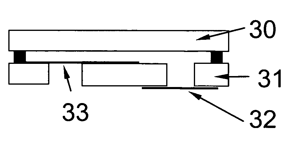
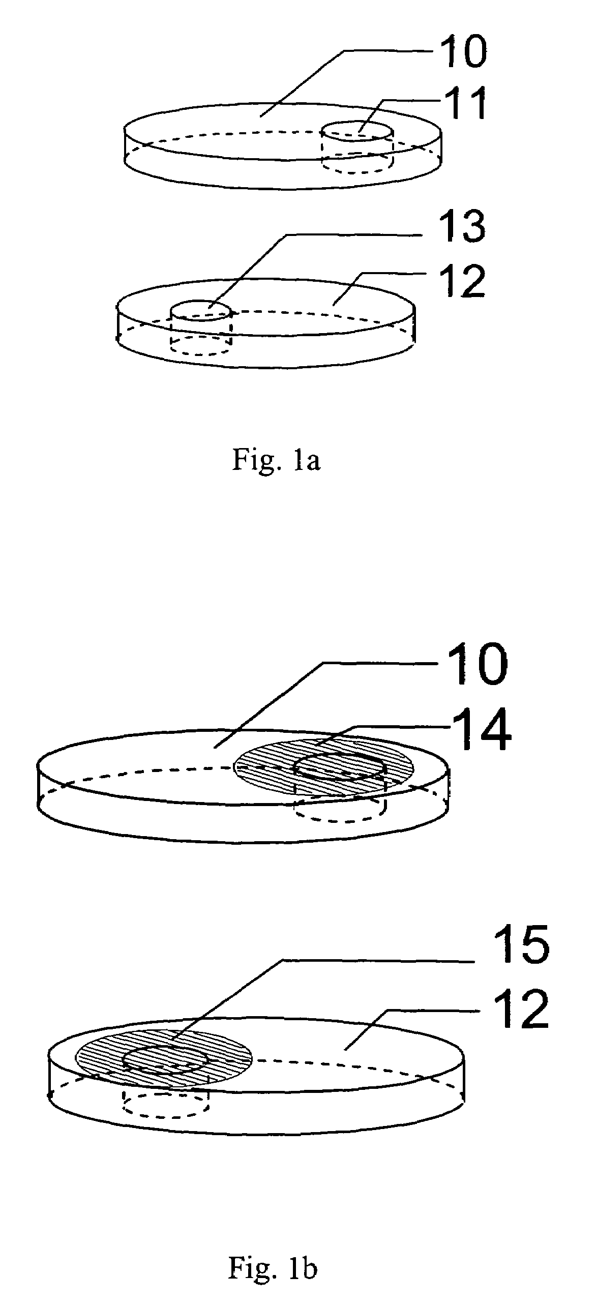
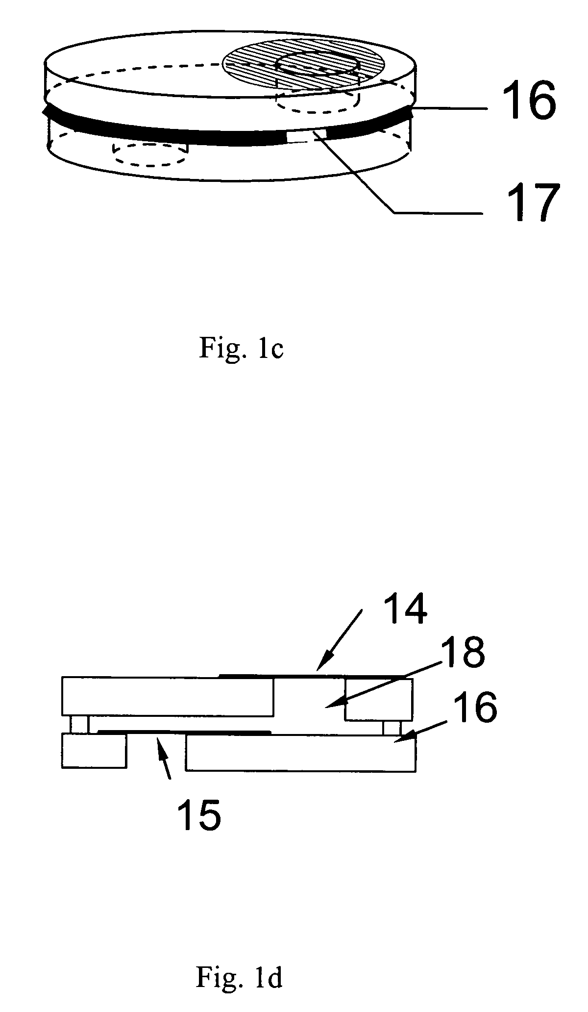
10top layer11reservoir hole12bottom layer13lens hole14top hole membrane cover15bottom hole membrane cover16adhesive17gap hole18cell chamber25 20top layer21bottom layer22top membrane cover23bottom membrane cover24liquid25ball-headed lever30top layer31bottom layer32right hole33right membrane cover34left hole35left membrane cover36liquid40upper layer41lens hole42convex lens50upper layer15 51lens hole52concave lens60top layer61bottom layer62right reservoir hole20 63lens hole64left reser...


PUM


Abstract

A variable focus liquid lens is formed using two substrates with at least two through holes in at least one of the substrates. One end of each through hole is covered with a distensible membrane, one on the exterior surface of the substrate and the other on the interior surface. The substrates are sealed about the periphery to form a chamber and the chamber is filled with a liquid material. When pressure is applied to the membrane the liquid in the chamber is redistributed to form the lens. The variable focus liquid-filled lens is formed by providing a first and second substrate, forming at least two through holes in at least one of the first and second substrate, sealing one end of each of the at least two holes with a flexible transparent membrane, and sandwiching a liquid in a chamber formed between the first and second substrate.

Description

[0001]This invention relates to optical focusing, in particular devices, methods, systems and apparatus for a liquid-based lens and associated zoom lens, wherein the focal length of the lens is variable.BACKGROUND AND PRIOR ART[0002]Adaptive-focus liquid lens has been used over the years for eyeglasses, cameras, projectors, cell phone as well as other machine vision applications. Based on the operating mechanisms and device structures, liquid lenses can be classified into three types. The first type is the liquid lens having a fixed volume of clear liquid which is sandwiched between a rigid lens (or a planar substrate) and a thin transparent elastic membrane, as described in U.S. Pat. Nos. 5,138,494, 5,999,328 and 6,040,947 issued to Kurtin et al. and U.S. Pat. No. 5,526,067 issued to Cronin et al. By moving the periphery of the elastic membrane, the liquid inside the lens assembly is redistributed such that the curvature of the film is changed. The changed curvature of the liquid l...

Claims


Application Information

Patent Timeline
06 May 2008
Publication
US7369321B1
IPC
G02B1/06
CPC
G02B3/0056; G02B3/14
Inventors
REN, HONGWEN; WU, SHIN-TSON