Dynamic random access memory device and method for self-refreshing memory cells

Active Publication Date: 2008-05-06
CONVERSANT INTPROP MANAGEMENT INC
View PDF7 Cites 17 Cited by
  • Summary
  • Abstract
  • Description
  • Claims
  • Application Information

AI Technical Summary

Benefits of technology

[0010]It is an object of the present invention to provide an improved dynamic random access memory (DRAM) having a self-refresh function and an improved method for self-refreshing the memory cells of a DRAM device.
[0013]Advantageously, the self-refresh request circuit performs arbitration function for critical timing situations between the oscillation signal and the self-refresh mode signal. For example, the arbitration function is achieved by a logic circuit having a latch circuit. The latch circuit detects the signal conflict and holds it until the next relevant transition of a pulse's logic state to provide a pulse of the self-refresh request signal. The arbitration function provided by the latch circuit prevents both a malfunction of the first self-refresh attempt after the entry of self-refresh mode and a malfunction of the last self-refresh attempt after the exit of the self-refresh mode.
[0018]In accordance with embodiments of the present invention, the generation of unpredictable self-refresh request pulse of narrow width is prevented. A reliable self-refresh request signal with a wide range of cell retention time due to the support by the free-run oscillation signal is provided. Additionally, a temperature compensation circuit can be added for controlling or adjusting the self-refresh period in accordance with changes to the temperature along with the free-running oscillator.

Problems solved by technology

The free-run oscillation signal is generated without synchronizing with the entry and exit of the self-refresh and there is a possible conflict between the oscillation signal and the self-refresh mode signal.

Method used


Image

  • Dynamic random access memory device and method for self-refreshing memory cells
  • Dynamic random access memory device and method for self-refreshing memory cells
  • Dynamic random access memory device and method for self-refreshing memory cells

Examples


Embodiment Construction

[0031]In the following detailed description of sample embodiments of the invention, reference is made to the accompanying drawings which form a part hereof, and in which is shown by way of illustration of specific sample embodiments in which the present invention may be practiced. These embodiments are described in sufficient detail to enable those of ordinary skill in the art to practice the present invention, and it is to be understood that other embodiments may be utilized and that logical, electrical, and other changes may be made without departing from the scope of the present invention. The following detailed description is, therefore, not to be taken in a limiting sense, and the scope of the present invention is defined by the appended claims.

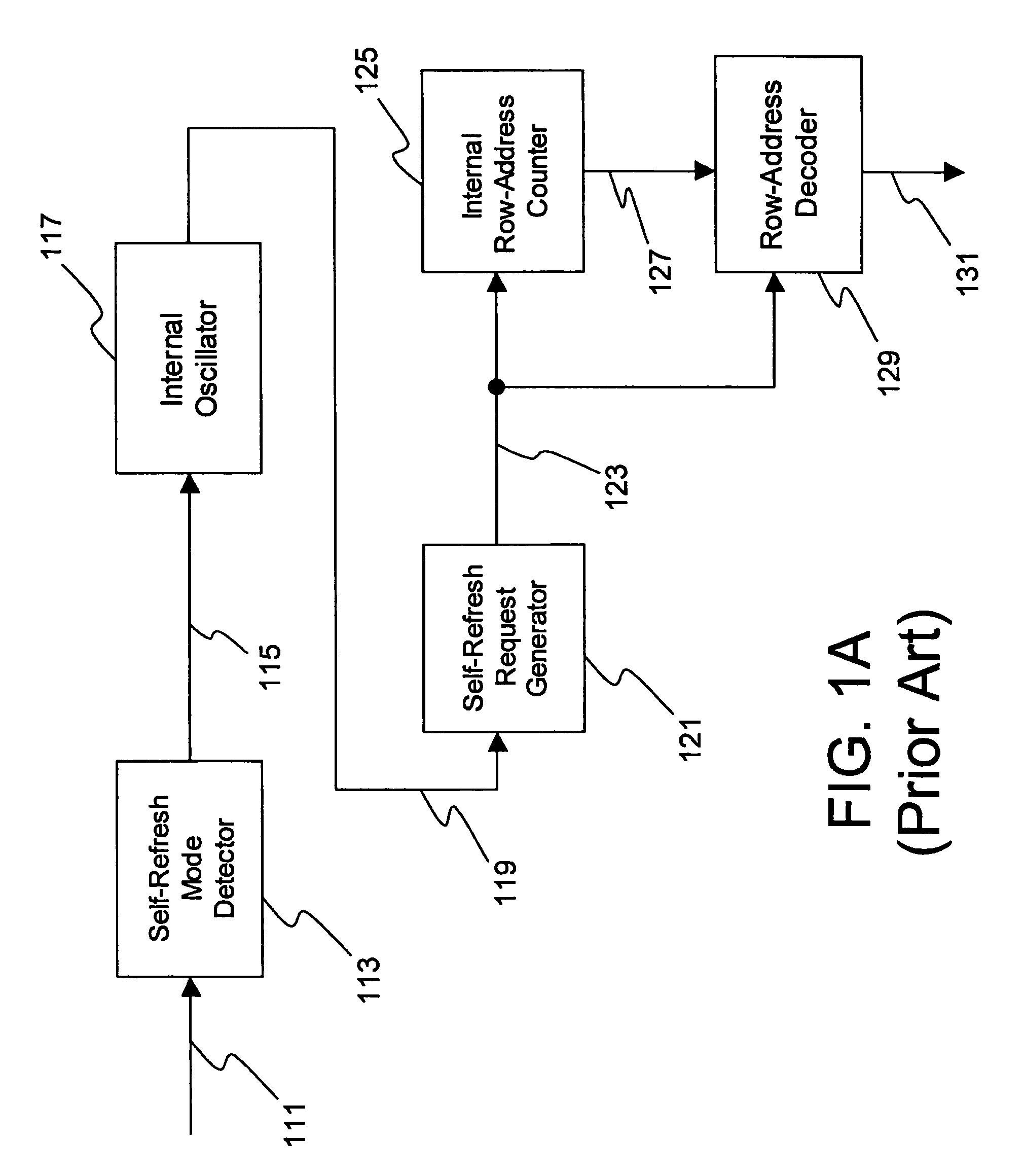
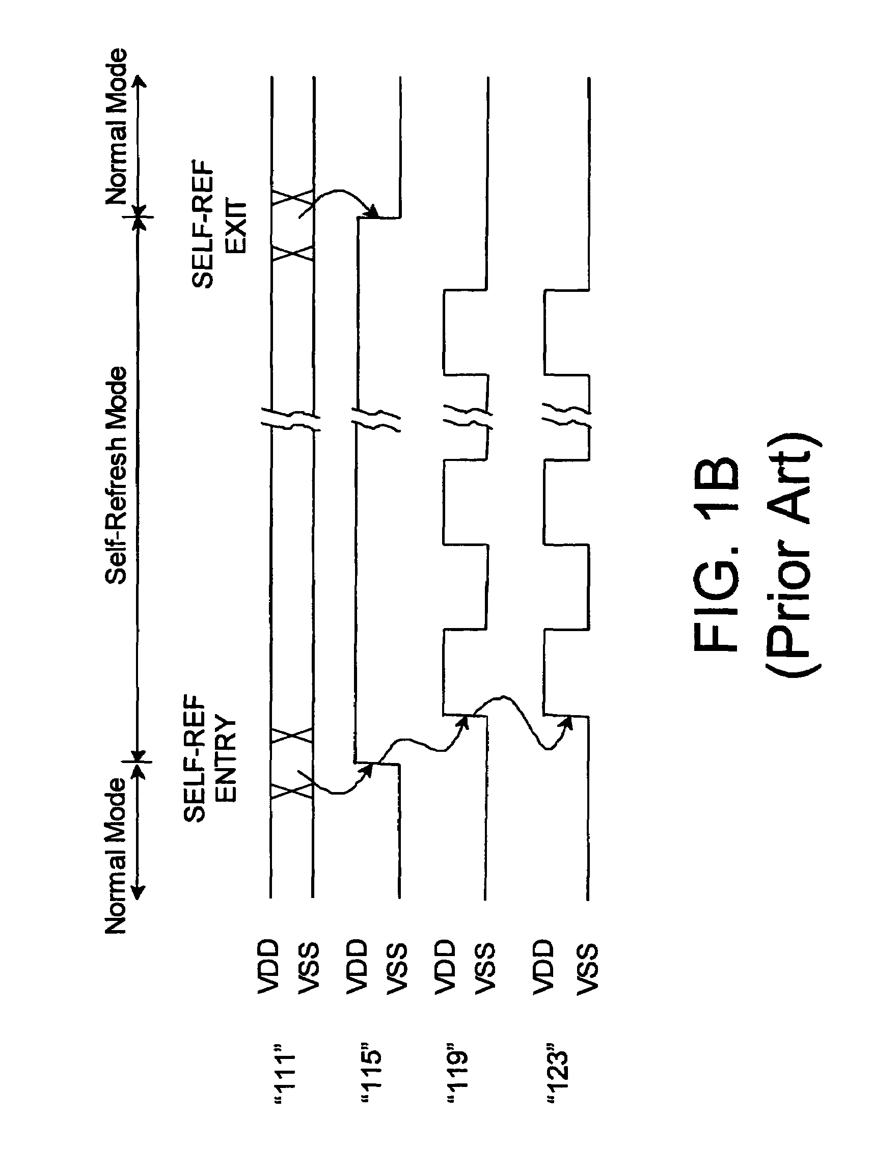
[0032]FIG. 1A shows a self-refresh controller found in conventional dynamic random access memories (DRAMs) and FIG. 1B shows the relative timing sequence for the signals of the DRAM device shown in FIG. 1A. Referring to FIGS. 1A and 1B, ...


PUM


Abstract

A dynamic random access memory (DRAM) device having memory cells is operated in a self-refresh mode and a normal mode. A mode detector provides a self-refresh mode signal in the self-refresh mode of operation. It includes a free-running oscillator for generating an oscillation signal independent of the self-refresh mode signal. In response to the oscillation signal, a self-request controller provides a self-refresh request signal in the self-refresh mode. The self-refresh signal is asynchoronized with the self-fresh mode signal and is provided to an address circuit to select a wordline for refreshing the memory cells thereof. The self-refresh request controller includes logic circuitry for arbitrating timing between initial active edges of the oscillation signal and the self-refresh mode signal and providing the self-refresh request and ceasing it, regardless of conflict between the self-refresh mode signal and the oscillation signal upon self-refresh mode entry and exit. The DRAM devices perform and achieve reliable self-refresh for variable DRAM cell retention time.

Description

TECHNICAL FIELD[0001]The present invention generally relates to a semiconductor integrated circuit and in particular to a dynamic random access memory device with a self-refresh function and a method for self-refreshing the data storage cells of a dynamic random access memory.BACKGROUND INFORMATION[0002]In dynamic random access memory (DRAM) integrated circuit devices, DRAM cell arrays are typically arranged in rows and columns such that a particular DRAM cell is addressed by specifying its row and column within the array. A wordline connects a row of cells to a set of bitline sense amplifiers that detect the data in the cells. In a read operation, a subset of the data in the sense amplifiers is then chosen, or “column-selected” for output. DRAM cells are “dynamic” in the sense that the stored data, typically in the form of charged and discharged storage capacitors, will dissipate after a relatively short period of time. Thus, in order to retain the information, the contents of the ...

Claims


Application Information

Patent Timeline
Patent Type & Authority Patents(United States)
IPC IPC(8): G11C7/00
CPCG11C7/04G11C11/406G11C11/40615G11C11/40626G11C11/401G11C11/402
Inventor OH, HAKJUNE
Owner CONVERSANT INTPROP MANAGEMENT INC
Why Eureka
Try Eureka