Digital audio signal processing

a digital audio and signal processing technology, applied in the field of digital audio signal processing, can solve the problems of louder audio, less quiet audio segments, and less listening to the audio, so as to reduce the likelihood of clipping, reduce intermodulation distortion, and reduce the effect of distortion

Active Publication Date: 2008-05-06
SONNOX
View PDF13 Cites 43 Cited by
  • Summary
  • Abstract
  • Description
  • Claims
  • Application Information

AI Technical Summary

Benefits of technology

[0017]The invention recognises that by applying a time-invariant transfer function of a predetermined form to a digital audio signal, the perceived loudness of the reproduced audio signal can be increased. The simple time-invariant transfer function of the sample mapping means that little hardware is required. The increase in perceived loudness can be achieved without increasing the amount of clipping in the reproduced signal.
[0020]It will be appreciated that the transfer function could take any form at the extremes of the input sample value range and at the origin. However it is preferred that the transfer function meets the unmodified response curve at these points. This has the advantages of reducing the likelihood of clipping and reducing distortions in the reproduced sound.
[0021]Although the sample mapping could be performed on an input sample sequence comprising a range of frequencies it is preferable to filter the input sample sequence into two or more different frequency bands and to perform the sample mapping separately on each frequency band. This has the advantage of reducing intermodulation distortion in the reproduced audio signal.
[0022]Although the sample mapping can be performed on every input digital audio signal it is advantageous to provide a user control to switch the sample mapping on or off according to user requirements.
[0023]Although the sample mapping can be performed according to a fixed predetermined time-invariant transfer function it is advantageous to provide a user-control to allow the user to modify a quasi time-invariant transfer function to suit the particular input digital audio source.

Problems solved by technology

The mapping of voltage values from a continuous range to a finite number of discrete levels results in quantisation error.
Since it has also been proposed that the highest peak will generally determine the comfortable listening level for the volume setting, a large dynamic range may mean that the quieter audio segments are too quiet for the listener to distinguish.
Compression typically results in the audio signal sounding louder on replay.
If the attack takes too long the signal may “clip” but if it happens too quickly the audio content loses dynamic impact for the listener.
Any excursions of the voltage level above the maximum output voltage will result in a distortion of the waveform known as “clipping”.

Method used


Image

  • Digital audio signal processing
  • Digital audio signal processing
  • Digital audio signal processing

Examples


first embodiment

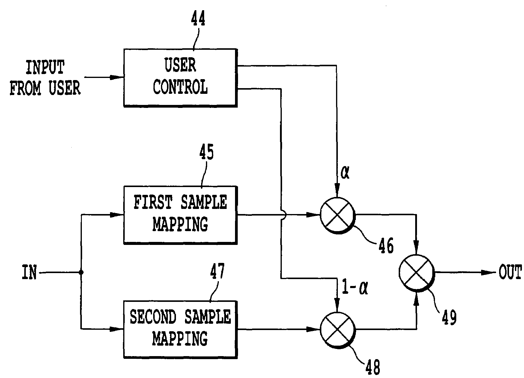
[0035]FIG. 3 is a schematic diagram of a digital audio signal processing apparatus according to the invention. An input digital audio signal is supplied to a first sample mapping module 45 that processes the input sample values to produce first output sample values according to a first predetermined transfer function. The first output sample values are input to first multiplier 46 which multiplies the first output sample values by a variable α to produce a first modified output sample value. The input digital audio signal is also supplied to a second sample mapping module 47 that processes the input sample values to produce second output sample values according to a second predetermined transfer function. The output of the second sample mapping module 47 is input to second multiplier 48 which multiplies this output by a variable 1−α to produce a second modified output sample value. User control 44 receives variable α from a user and supplies this variable to first multiplier 46 and ...

second embodiment

[0046]FIG. 5 illustrates a digital audio signal processor according to the invention. An input digital audio signal is supplied to each of three infinite impulse response (IIR) filters 50, 60, 70 connected in parallel. A first IIR filter 50 passes a high frequency band signal; a second IIR filter 60 passes a medium frequency band signal; and a third IIR filter 70 passes a low frequency band signal L. In this embodiment the low frequency band L corresponds to frequencies less than 240 Hz, the mid frequency band M corresponds to 240 Hz-2400 Hz and the high frequency band H corresponds to frequencies greater than 2400 Hz.

[0047]The high frequency band signal H is supplied to a sample mapping module 80 where it is processed according to the time invariant transfer function of FIG. 4A to produce an output signal H*. The low frequency band signal L is supplied to a sample mapping module 100 where it is processed according to the time invariant transfer function of FIG. 4A to produce an out...


PUM

PropertyMeasurementUnit
sampling frequencyaaaaaaaaaa
frequenciesaaaaaaaaaa

Abstract

A digital audio processor comprises at least one digital audio sample mapping module and produces a sequence of output digital audio sample values by applying a quasi time-invariant transfer function to each input digital audio sample value, the transfer function being arranged so that a ratio of root mean square signal level to peak signal magnitude is lower for the input digital audio signal than for a corresponding portion of the output digital audio signal.

Description

BACKGROUND OF THE INVENTION[0001]1. Field of the Invention[0002]This invention relates to the processing of digital audio signals.[0003]2. Description of the Prior Art[0004]Many modern audio signal processing devices perform audio processing operations on sampled digital audio signals rather than on analogue signals. Digital audio signals which signify discrete and clearly defined voltage levels have the advantage over analogue signals that they can be repeatedly copied without any degradation of the audio signal quality. Furthermore, error correction techniques can be applied to digitally encoded data prior to reproduction and some types of noise can be removed. Once an audio signal has been stored in digital form the data is not restricted to a particular time domain but can be manipulated and processed at will. The compact disc is an example of a digital audio storage device.[0005]An analogue audio signal can be converted to its digital equivalent using a technique known as pulse...

Claims


Application Information

Patent Timeline
Patent Type & Authority Patents(United States)
IPC IPC(8): G06F17/00H03G3/00G11B20/10G10L19/00G10L21/034G11B20/04H03G7/00H03G9/02
CPCH03G7/007H03G9/005H03G9/025
Inventor FRINDLE, PAUL ANTHONY
Owner SONNOX
Why Eureka
Try Eureka