Controlled magnetohydrodynamic fluidic networks and stirrers

a fluidic network and magnetohydrodynamic technology, applied in positive displacement liquid engines, laboratory glassware, machines/engines, etc., can solve the problems of significant heating of the solution, difficult insertion of moving components into these devices, and lack of effective means for either the control of liquid movement and movemen

Active Publication Date: 2008-05-13
THE TRUSTEES OF THE UNIV OF PENNSYLVANIA
View PDF5 Cites 7 Cited by
  • Summary
  • Abstract
  • Description
  • Claims
  • Application Information

AI Technical Summary

Benefits of technology

[0019]One aspect of the present invention is a controlled, magnetohydrodynamically-driven, fluidic network comprising a plurality of connected and individually controlled conduits each having at least one pair of opposing walls and at least one pair of electrodes disposed along the opposing walls, and at least one electrode controller in operational engagement with the electrodes for implementing an activation sequence comprising a current or potential across electrode pairs. In a preferred embodiment, the network further comprises an algorithm for determining the activation sequence. In operation, the fluidic network is provided with an at least slightly conductive fluid, is placed at least partially within a suitable magnetic field, and an electric field of a specific current or potential is applied for a predetermined period of time across electrode pairs and through the fluid within the network. In accordance with MHD principles, the magnetic field is oriented approximately perpendicular both to the orientation of the electric field and to the axis of flow along the conduit. Interaction of the electric and magnetic fields generate volumetric forces, called Lorentz body forces that propel the fluid through the network. By the selective application of electric fields of specific currents or potentials at various points in the network for specific time intervals, the fluid may be directed with precision through the network in any desired pattern without the need for moving parts such as mechanical pumps or valves. In this manner, the control and flow of fluid through the network is similar to the control and flow of an electrical current in an electronic circuit.

Problems solved by technology

In a micro-scale device such as a laboratory on a chip, mixing of fluids is a particular challenge as flows are at very low Reynolds numbers, turbulence is not available to promote mixing, and the insertion of moving components into these devices is difficult.
These forces usually induce only very low flow rates, require the use of high electrical potentials, and can often cause significant heating of the solution which may be inappropriate for the materials being used or the reactions to be performed.
These efforts, however, have addressed individual pumping devices and have not provided an effective means for either the controlled movement of liquids through a microfluidic network or the efficient mixing of liquids in such microscale environments.

Method used


Image

  • Controlled magnetohydrodynamic fluidic networks and stirrers
  • Controlled magnetohydrodynamic fluidic networks and stirrers
  • Controlled magnetohydrodynamic fluidic networks and stirrers

Examples


Embodiment Construction

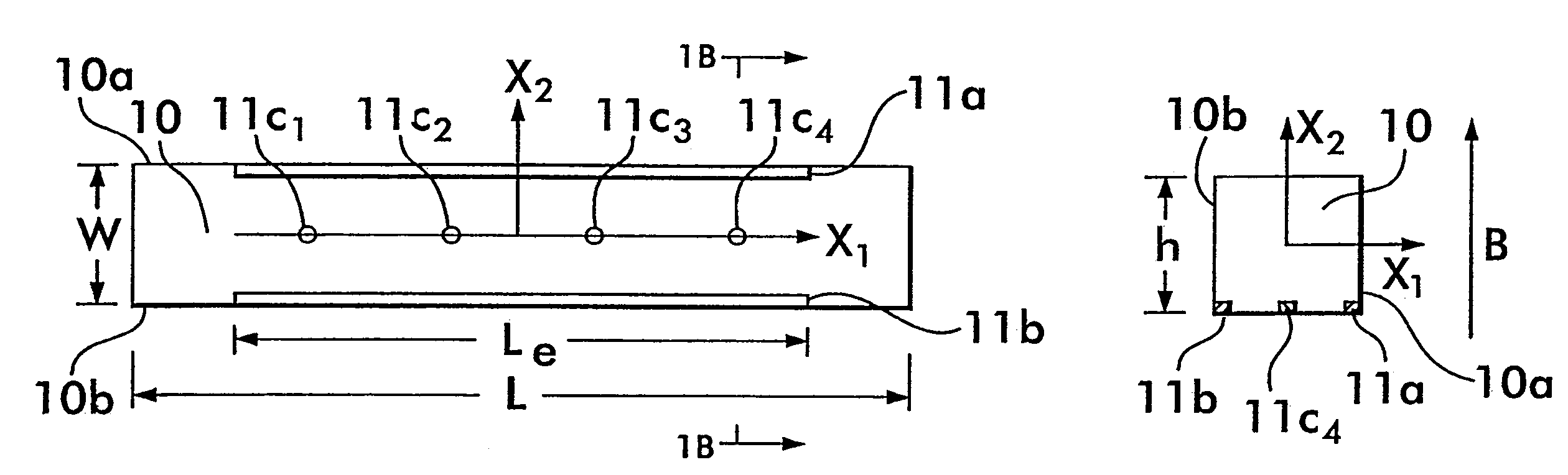
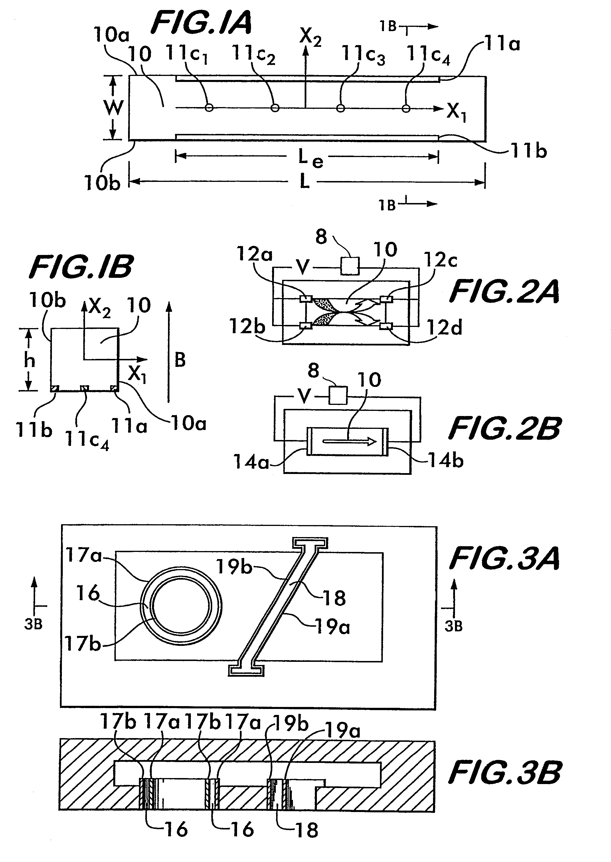
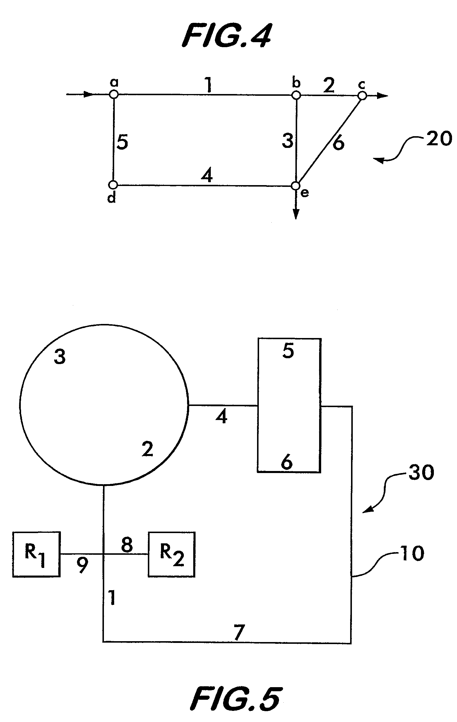
[0043]Controlled-flow MHD fluidic networks, thermal cyclers, and chaotic advection stirrers for use in microfluidic devices for processing and analyzing biological and chemical samples such as laboratories on chips and micro-total analysis systems are described.

[0044]The controlled-flow MHD fluidic network comprises a plurality of connected and individually controlled conduits for the transmission of fluid each conduit having a pair of opposing walls, at least one pair of electrodes disposed along the opposing walls of the conduits, and at least one electrode controller in operational engagement with the electrodes for implementing an activation sequence of currents or potentials across the electrode pairs. In preferred form, the network further comprises an algorithm for determining the activation sequence. Movement of fluid through the network is accomplished in accordance with principles of magnetohydrodynamics which utilize the interaction of approximately perpendicularly orient...


PUM


Abstract

The present invention relates to controlled, magnetohydrodynamically-driven, fluidic networks containing a plurality of individually controlled branches. The branches consist of conduits equipped with pairs of electrodes that are controlled by electrode controllers. In operation, the network is placed within a magnetic field and potentials or currents are applied across electrode pairs within the various branches of the network in specifically determined magnitudes and polarities for specifically determined time intervals in accordance with an activation sequence that may be determined by an algorithm. Placed within a temperature gradient, at least a part of the network can act as a thermal cycler for use in biological interactions that employ temperature variations. The invention also relates to magnetohydrodynamic stirrers comprising a conduit or cavity having at least two electrodes disposed in such an orientation that, upon the application of a potential or current across the electrode pair within a magnetic field, secondary flows such as chaotic advection is generated.

Description

CROSS-REFERENCE TO RELATED APPLICATION[0001]Applicant claims the benefit of provisional Application No. 60 / 409,359, filed Sep. 9, 2002, which is incorporated herein in its entirety.GOVERNMENT LICENSE RIGHTS STATEMENT[0002]This invention was supported by funds from the U.S. Government (DARPA Grant No. N66001-97-1-8911 and DARPA Grant No. N66001-01-C-8056). The U.S. Government may therefore have certain rights in the invention.FIELD OF THE INVENTION[0003]The invention relates to controlled, magnetohydrodynamically-driven, fluidic networks suitable for use in devices for processing and analyzing biological and chemical samples such as laboratories on chips and micro-total analysis systems. Placed within a temperature gradient, the fluidic networks of the present invention can further act as thermal cyclers, particularly of the type used for polymerase chain reactions (PCR). The invention also relates to magnetohydro-dynamic stirrers that are capable of generating chaotic advection with...

Claims


Application Information

Patent Timeline
Patent Type & Authority Patents(United States)
IPC IPC(8): H02K44/02B01F13/00B01L3/00B01L7/00F04B19/00
CPCB01F13/0077B01L3/5027B01L3/50273F04B19/006B01L7/525B01L7/54B01L2300/0816B01L2300/0874B01L2400/043B01F33/3032
Inventor BAU, HAIM H.
Owner THE TRUSTEES OF THE UNIV OF PENNSYLVANIA
Why Eureka
Try Eureka