
Ceramics heater

a ceramic heater and heater body technology, applied in the field of ceramic heaters, can solve the problems of grain boundary cracks, poor temperature uniformity of conventional ceramic heaters, and poor temperature uniformity of conventional ceramic heaters, and achieve the effect of satisfying temperature uniformity and stable heating valu

Inactive Publication Date: 2008-05-13
NHK SPRING CO LTD
View PDF23 Cites 31 Cited by
  • Summary
  • Abstract
  • Description
  • Claims
  • Application Information

AI Technical Summary

Benefits of technology

[0016]Accordingly, the object of the present invention is to provide a ceramics heater that enjoys satisfactory temperature uniformity and a stable heating value.
[0017]A ceramics heater according to the invention comprises a heater plate formed of ceramics and a metal foil heater wire formed of a high-melting metal, having a thickness of 100 μm to 175 μm, and embedded in the heater plate. According to the invention, the metal foil heater wire that is longer enough than that of a conventional ceramics heater can be embedded in the heater plate. Thus, the temperature uniformity of the heater plate is improved. According to the invention, grain boundary cracks that may be formed in the surface layers of the heater wire when the ceramics is sintered can be prevented from affecting the entire profile of the heater wire. Accordingly, variation of the heating value that is attributable to cracking of the heater wire can be restrained.
[0018]The heater plate is formed of aluminum nitride (AlN), for example. The metal foil heater wire of the invention has a thickness of 100 μm or more. If the heating value is fixed, therefore, the heater wire can be made longer than a conventional metal foil heater wire (50 μm or less in thickness). According to this arrangement, the temperature uniformity of the heater plate of aluminum nitride can be improved, and variation of the heat release value attributable to cracking of the heater wire can be restrained.
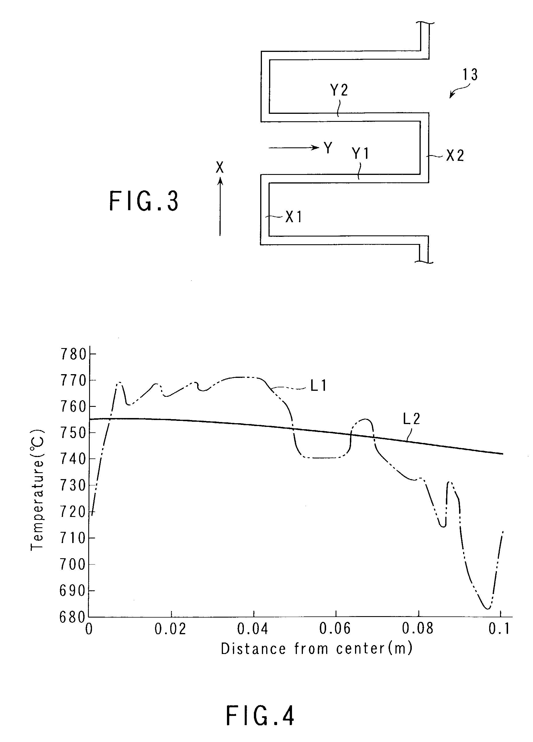
[0019]The metal foil heater wire is formed flush in zigzags, for example. According to this arrangement, the long metal foil heater wire can be laid out on the same plane in the heater plate, so that the temperature uniformity can be further improved.
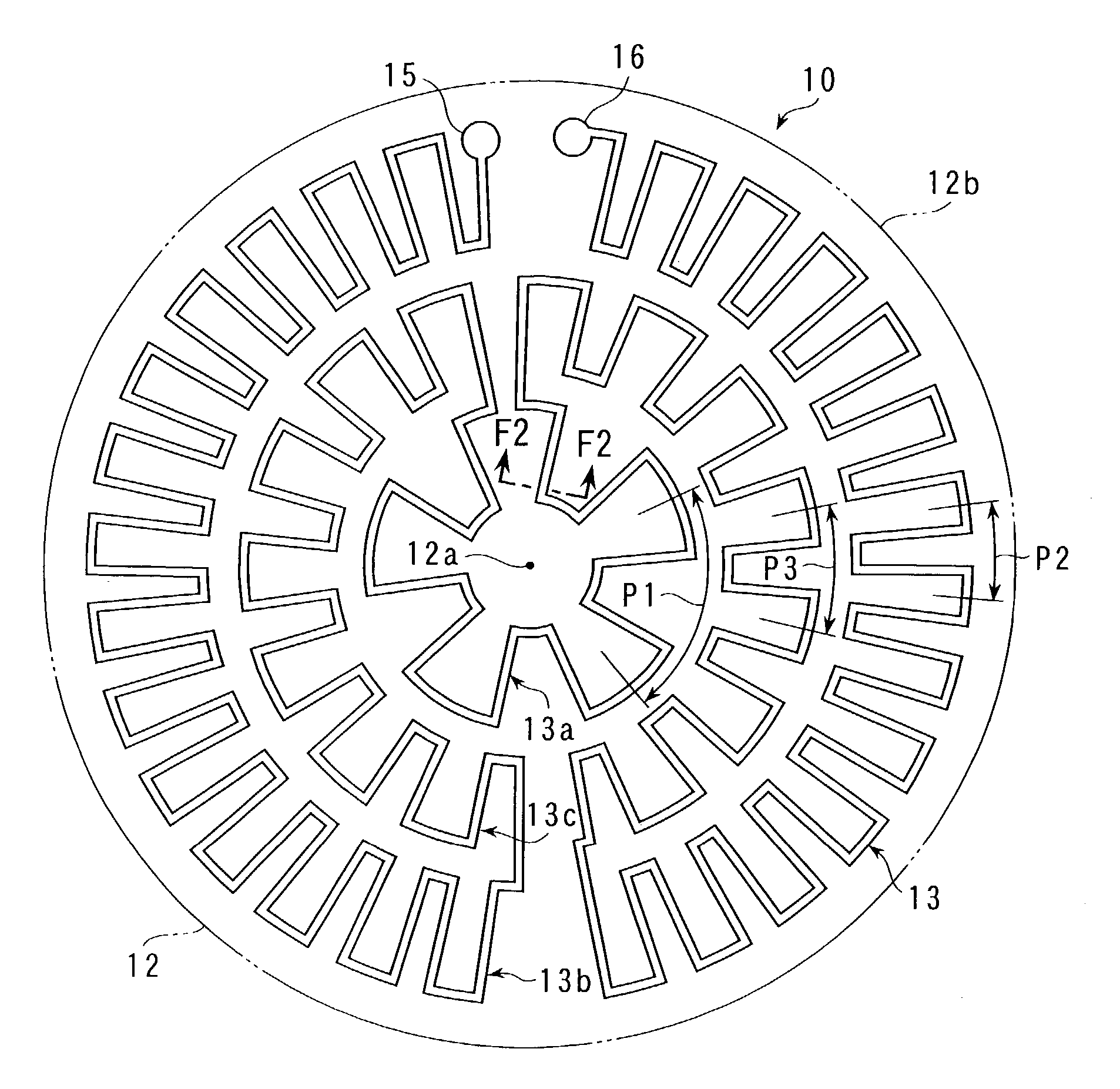
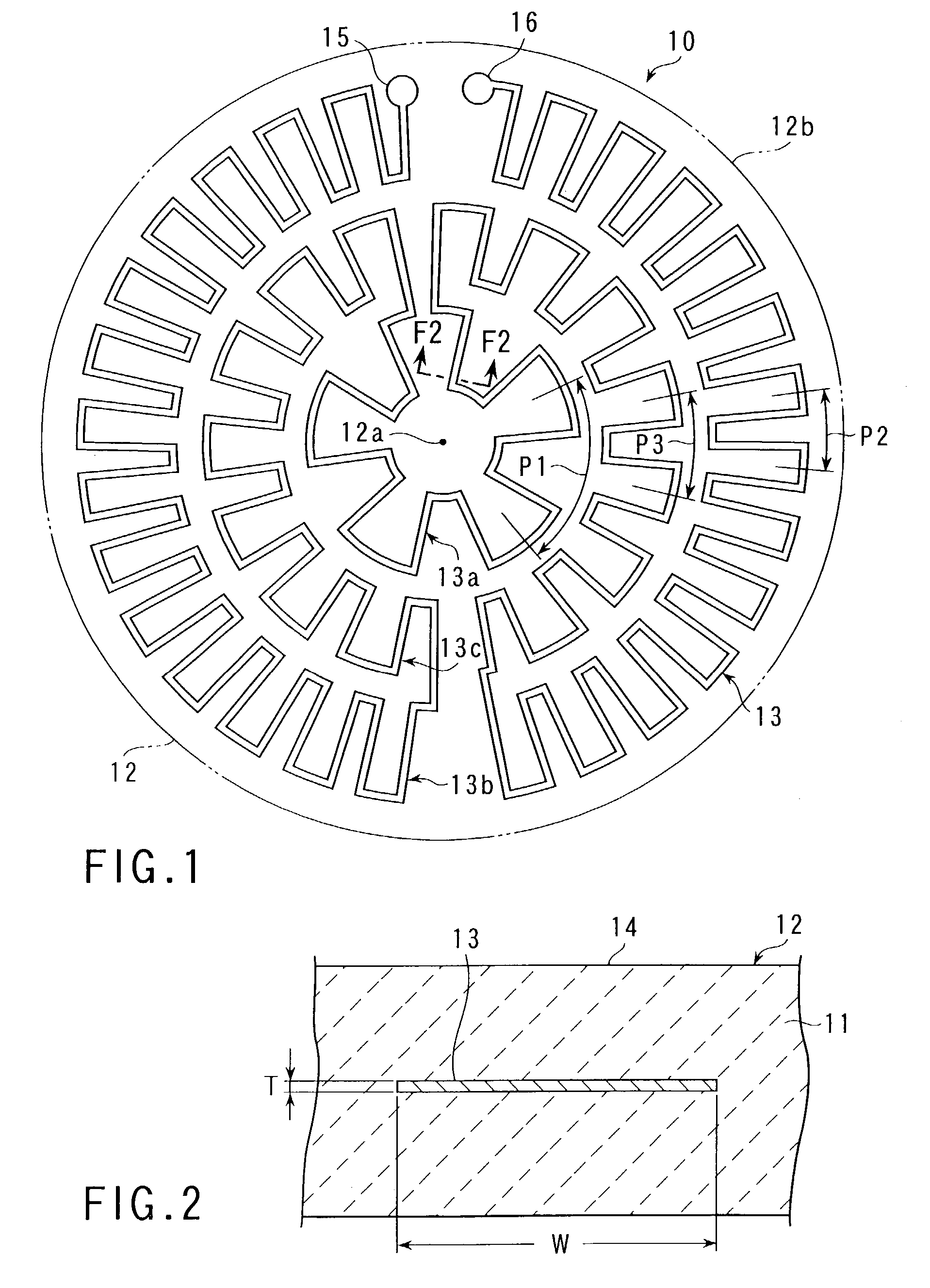
[0020]Preferably, in order to improve the temperature uniformity of the heater plate additionally, the metal foil heater wire includes an inside portion located near the center of the heater plate and formed in zigzags at first pitches in the circumferential direction of the heater plate and an outside portion located near the outer periphery of the heater plate and formed in zigzags at second pitches in the circumferential direction of the heater plate, the second pitches being shorter than the first pitches. According to this arrangement, the diametrical temperature distribution of the heater plate can be made more uniform.

Problems solved by technology

Possibly, the ceramics heaters involve the following problems.
Thus, the conventional ceramics heater is poor in temperature uniformity.
The heater plate for heating wafers in the semiconductor manufacturing processes, in particular, requires the maintenance of uniform temperature distribution, so that unevenness in its temperature is a serious problem.
In the process of embedding the heater wire in ceramics material powder and sintering it, its surface layers react with carbon in the ceramics material and are carbonized, so that they may possibly suffer grain boundary cracks.
If the heater wire suffers the aforesaid grain boundary cracks, its electrical resistance is caused to exceed a normal value in the process of sintering the ceramics material powder.
If the electrical resistance of the heater wire becomes higher, sufficient current cannot flow, so that the temperature characteristics of the ceramics heater are adversely affected.
If the load density is high, the heater wire may possibly snap during use (or when it is supplied with current).
Since the heater wire is thin, moreover, variation of its thickness causes substantial fluctuations of the heating value and exerts a bad influence upon the temperature uniformity.
Possibly, furthermore, the heater wire may snap when it is embedded in the ceramics material or sintered unless it is embedded carefully.

Method used


Image

  • Ceramics heater
  • Ceramics heater
  • Ceramics heater

Examples


Embodiment Construction

[0031]An embodiment of the present invention will now be described with reference to FIGS. 1 to 6.

[0032]As shown in FIGS. 1 and 2, a ceramics heater 10 comprises a substantially circular heater plate 12, formed of ceramics 11 such as aluminum nitride, and a metal foil heater wire 13 embedded in the plate 12. The heater plate 12 is formed by sintering ceramics material powder into a given shape. In FIG. 1, the heater plate 12 is shown only in outline.

[0033]The ceramics heater 10 is used in a semiconductor manufacturing device or a thin-film manufacturing device for glass substrates, for example. The upper surface of the heater plate 12 forms a flat work bearing surface 14 that can support a work such as a semiconductor wafer thereon. The heater plate 12 has a diameter of about 250 mm and a thickness of 15 mm to 30 mm, for example. Since these dimensions are suitably set according to the specifications, such as dimensions, of the work to be heated, however, they are not limited to the...


PUM


Abstract

A ceramics heater comprises a circular heater plate formed of aluminum nitride and a metal foil heater wire formed of a high-melting metal and having a thickness of 100 μm to 175 μm. The heater wire is embedded in the heater plate. The heater wire has an inside portion located near the center of the heater plate and formed in zigzags at first pitches in the circumferential direction of the heater plate and an outside portion located near the outer periphery of the heater plate and formed in zigzags at second pitches in the circumferential direction of the heater plate. The second pitches are shorter than the first pitches.

Description

CROSS-REFERENCE TO RELATED APPLICATIONS[0001]The entire contents Japanese Patent Application No. 2001-188285, filed Jun. 21, 2001, are incorporated herein by reference.BACKGROUND OF THE INVENTION[0002]1. Field of the Invention[0003]The present invention relates to a ceramics heater used to heat works such as wafers, glass substrates, etc. in semiconductor manufacturing processes or the like, for example.[0004]2. Description of the Related Art[0005]Ceramics heaters for heating wafers are used to perform CVD (chemical vapor deposition), PVD (plasma vapor deposition), etching, etc. in semiconductor manufacturing processes. The ceramics heaters are also used in filming apparatuses for forming thin films on glass substrates.[0006]A conventional ceramics heater, such as the one described in Jpn. Pat. Appln. No. 3011528, includes a heater plate of ceramics, a metal foil heater wire embedded in the heater plate, etc. The heater plate is formed of a sintered product of silicon nitride or alu...

Claims


Application Information

Patent Timeline
Patent Type & Authority Patents(United States)
IPC IPC(8): H05B3/68H05B3/14
CPCH05B3/143
Inventor TACHIKAWA, TOSHIHIROMIYAHARA, JUNICHIHANAMACHI, TOSHIHIKO
Owner NHK SPRING CO LTD
Learn More