Electric drive control apparatus and method

a technology of electric drive and control apparatus, which is applied in the direction of driver interaction, program control, gas pressure propulsion mounting, etc., can solve the problems of increasing the cost of the electric drive apparatus and insufficient motor torque, and achieve the effect of increasing the cost of the electric drive apparatus and sufficient motor torqu

Inactive Publication Date: 2008-05-13
AISIN AW CO LTD
View PDF25 Cites 9 Cited by
  • Summary
  • Abstract
  • Description
  • Claims
  • Application Information

AI Technical Summary

Benefits of technology

[0010]However, in the electric drive apparatus employing a low-resolution pulse generating-type sensor in accordance with the related art, if the rotation speed of the electric motor, that is, the motor rotation speed, is low, it becomes difficult to detect the magnetic pole position, so that sufficient motor torque cannot be generated. The employment of an electric motor of high rating is conceivable as a countermeasure, but increases the cost of the electric drive apparatus.
[0011]It is an object of the invention to solve, at least, the aforementioned problems of the related-art electric drive apparatus and provide an electric drive apparatus, an electric drive control apparatus and an electric drive control method that allow a reduction in the apparatus size, and that are capable of generating sufficient torque while reducing the cost.

Problems solved by technology

However, in the electric drive apparatus employing a low-resolution pulse generating-type sensor in accordance with the related art, if the rotation speed of the electric motor, that is, the motor rotation speed, is low, it becomes difficult to detect the magnetic pole position, so that sufficient motor torque cannot be generated.
The employment of an electric motor of high rating is conceivable as a countermeasure, but increases the cost of the electric drive apparatus.

Method used


Image

  • Electric drive control apparatus and method
  • Electric drive control apparatus and method
  • Electric drive control apparatus and method

Examples


Embodiment Construction

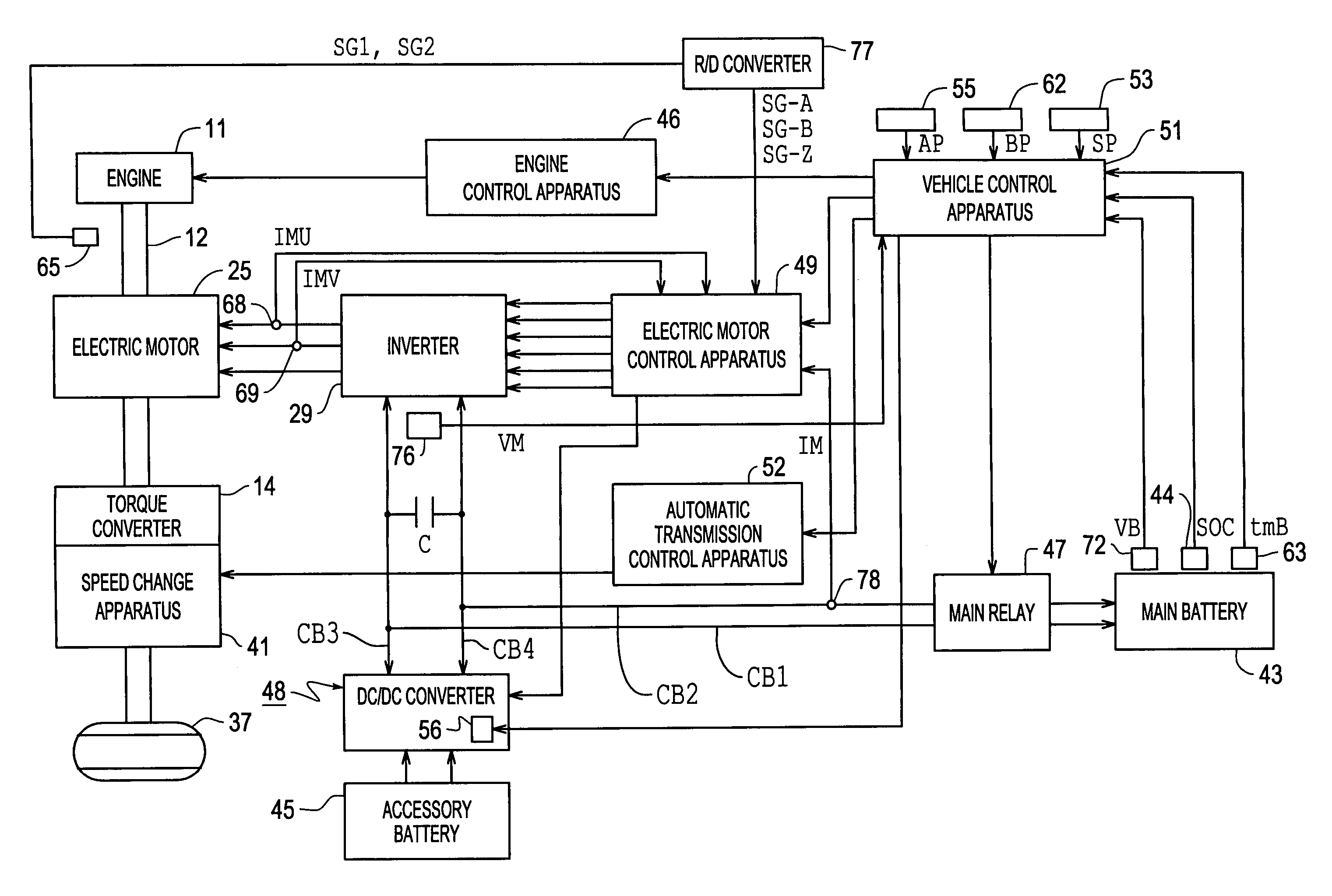
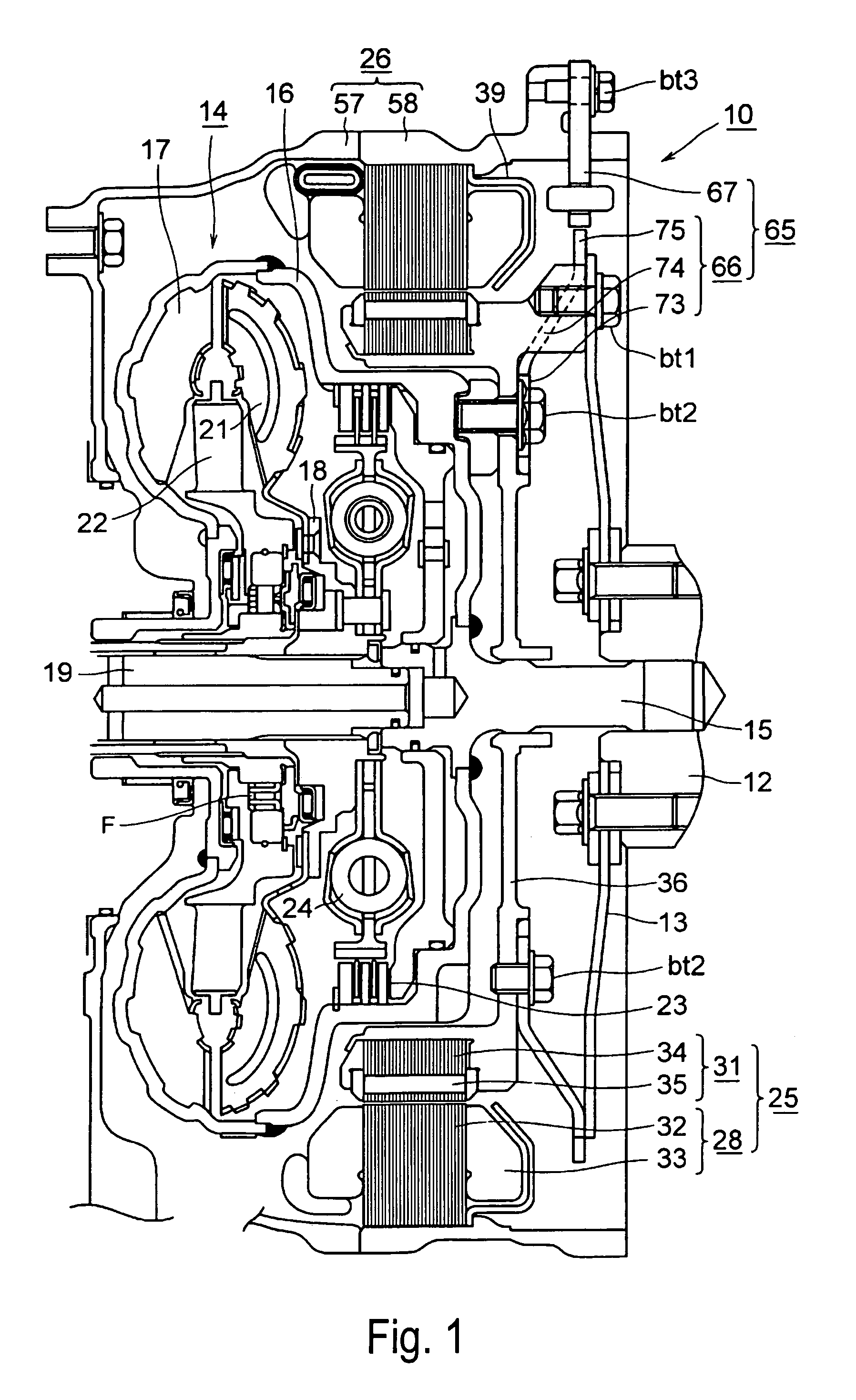
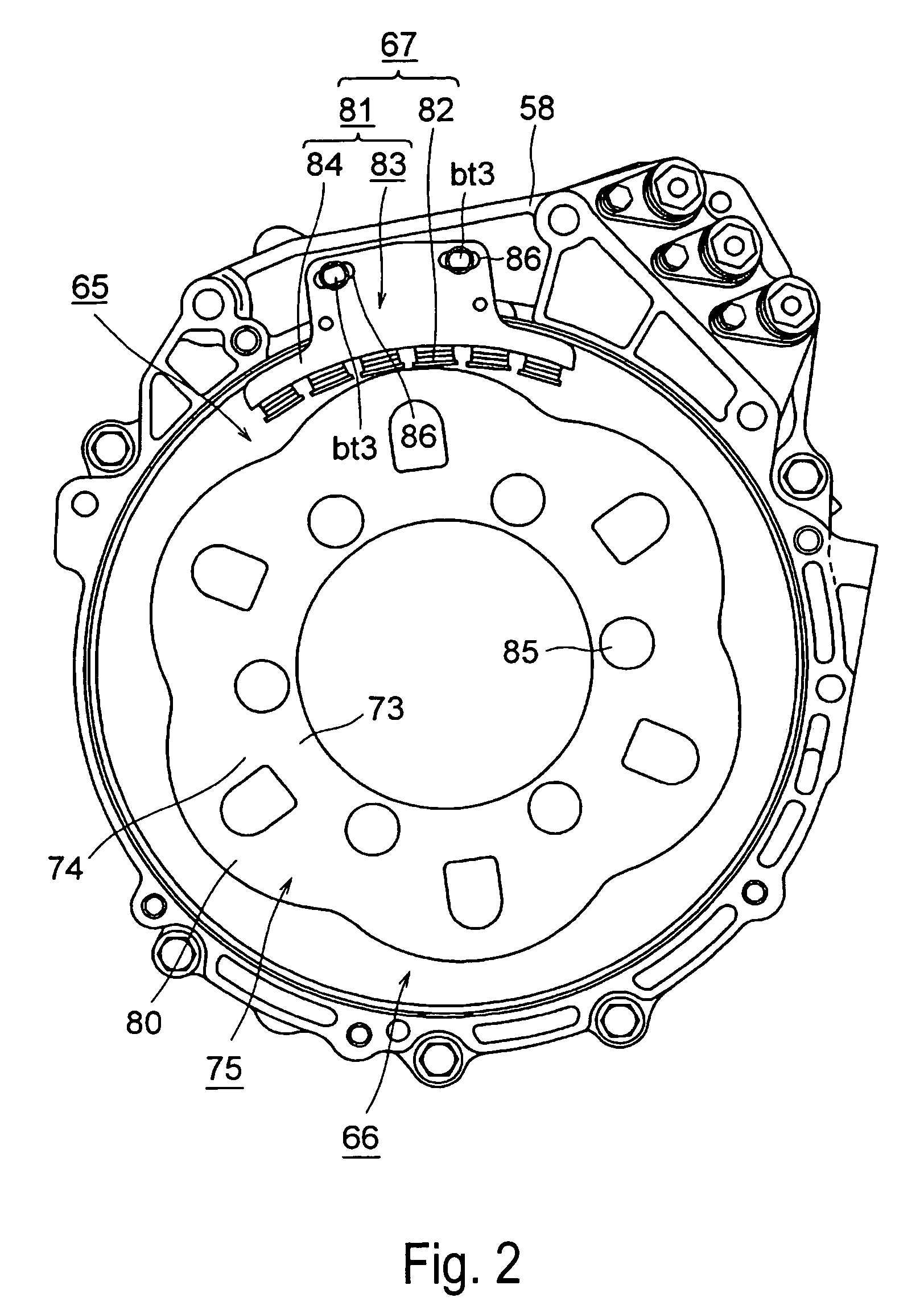
[0044]Description will be made in conjunction with a hybrid vehicle as an electric drive vehicle. In the drawings, reference numeral 10 denotes an electric drive apparatus; reference numeral 12 denotes a crankshaft as an output of an engine 11; reference numeral 13 denotes a drive plate; reference numeral 14 denotes a torque converter as a fluid transmission apparatus; reference numeral 25 denotes an electric motor as a generator-motor that has the functions of a generator and a motor; and reference numeral 26 denotes an electric drive apparatus case. The torque converter 14 includes a center piece 15, a front cover 16 connected to the center piece 15, a pump impellor 17 connected to the front cover 16, a turbine runner 21 that faces the pump impellor 17, that forms a torus together with the pump impellor 17, and that is connected to an input shaft 19 of a speed change apparatus 41 via a turbine hub 18, a stator 22, a lockup clutch device 23 disposed so as to be engageable and disen...


PUM


Abstract

An electric drive apparatus has an electric motor having a rotor and a stator; and a magnetic pole position detecting portion having a sensor rotor attached to the rotor, and a sensor stator that is adjacent to the stator, and that is fixed to a case, and that extends over a partial region of the sensor rotor extending in a circumferential direction. Because the sensor rotor of the magnetic pole position detecting portion is attached to the rotor and the sensor stator is adjacent to the stator and is fixed to the case, it is no longer necessary to use an all-round embracing type magnetic pole position detecting portion that embraces the entire shaft of an electric machine.

Description

CROSS-REFERENCE TO RELATED APPLICATION[0001]The disclosure of Japanese Patent Application No. 2003-207388 filed on Aug. 12, 2003 including the specification, drawings and abstract is incorporated herein by reference in its entirety.BACKGROUND OF THE INVENTION[0002]1. Field of Invention[0003]The invention relates to an electric drive apparatus, an electric drive control apparatus, and an electric drive control method.[0004]2. Description of Related Art[0005]In a related-art apparatus, an electric drive apparatus is mounted in an electric motor vehicle, which is an electric drive vehicle, so as to cause generation of torque of an electric motor that acts as an electric machine, that is, motor torque, and transfers the motor torque to driving wheels. The electric motor receives direct current from the battery, and is therefore driven to generate the motor torque during powering (driving). During regenerative operation (power generation), the electric motor receives torque due to the in...

Claims


Application Information

Patent Timeline
Patent Type & Authority Patents(United States)
IPC IPC(8): H02P6/16G01P3/00B60K6/26B60K6/485B60K6/547B60L50/16B60W10/06B60W10/08B60W20/00F02N11/00H02K7/00H02K11/00
CPCB60K6/26B60K6/485B60K6/547B60W10/08H02K7/006H02K11/0031B60L11/14B60L11/1861B60L15/20B60K6/405B60L2250/26H02K29/12Y02T10/6226B60L2210/10B60L2210/40B60L2240/421B60L2240/423B60L2240/545B60L2240/547B60L2240/549B60L2240/80H02K11/225Y02T10/70B60L50/16B60L58/12Y02T10/62Y02T10/64Y02T10/72Y02T10/7072
Inventor YAMAGUCHI, YASUOKOBAYASHI, YASUHIKO
Owner AISIN AW CO LTD
Why Eureka
Try Eureka