Apparatus for braking a synchronous machine

a synchronous machine and apparatus technology, applied in the direction of dc motor stoppers, ac motor stoppers, stopping arrangements, etc., can solve the problems of reducing the service life of the synchronous machine, and requiring additional components. the effect of reducing the construction complexity, improving the thermal loading of the power breakers, and simple way

Active Publication Date: 2008-05-13
B&R IND AUTOMATION GMBH
View PDF20 Cites 14 Cited by
  • Summary
  • Abstract
  • Description
  • Claims
  • Application Information

AI Technical Summary

Benefits of technology

[0007]In accordance with the invention, the short-circuit current in the armature windings is regulated in a pulse-width-controlled manner. This is achieved in such a way for example that power breakers short the armature windings depending on the short-circuit duration by the closed-loop control. The short-circuit current can be predetermined with the help of pulse-width modulation in such a way that the desired braking moment is obtained in an especially simple way. This allows not only keeping the braking moment virtually constant over the entire speed range, but also offers the possibility to brake in an especially simple way with every torque smaller than the maximum one, because it may occur in a number of applications that damage will occur in the mechanism coupled via the motor shaft of the synchronous machine by too strong braking. Any excessively strong rise of the short-circuit current can also be remedied elegantly with the closed-loop control in accordance with the invention, which thus securely prevents any exceeding of the permissible short-circuit current and thus a demagnetization of permanent magnets. A further advantage of the closed-loop control in accordance with the invention is that after an occurred short-circuit braking, a short-circuit braking can be initiated directly thereafter and it is not necessary to wait for any cooling period, as is the case in dynamic braking in accordance with the state of the art.
[0009]It is especially advantageous when the power breakers of two half-bridges of the converter which short the armature windings can be triggered in an alternating fashion by way of a closed-loop control device depending on the difference between the setpoint value of the short-circuit current corresponding to the setpoint value of the braking moment and the actual value of the short-circuit current. As a result, both the half-bridge for positive half-waves and the half-bridge for negative half-waves of the power converter can be used as short-circuit elements, thus ensuring an improved thermal loading of the power breakers. The braking output is carried off according to this embodiment of the invention thus in an especially simple way via the power converter which can generally be highly loaded in a thermal respect, the armature windings and an optionally provided braking resistor. As a result, the constructional complexity is minimized and only very few additional measures need to be provided for the braking operation of a synchronous machine in accordance with the invention.
[0010]As an alternative to the above embodiment of a synchronous machine, a synchronous machine with a rotor and an armature winding, which can optionally be shorted via a braking resistor according to a further advantageous embodiment of the invention, can be characterized in that the armature windings are connected to a rectifier circuit which can be shorted by way of a power breaker and that the power breaker can be triggered via a closed-loop control device depending on the difference between the setpoint value of the short-circuit current corresponding to the setpoint value of the braking moment and the actual value of the short-circuit current. According to this embodiment of a synchronous machine in accordance with the invention, the short circuit for the armature windings is produced by way of a separate power semiconductor circuit. The short-circuit current of the armature windings is rectified in the rectifier circuit and the outputs for positive and negative half-waves are then shorted via a power breaker and optionally a braking resistor. A relevant advantage of this synchronous machine in accordance with the invention is that the function of the braking device can be checked in an especially simple manner in a continuous or intermittent way. This is especially advantageous when high requirements are placed on the continuous availability of the braking device. A control unit which is separately provided can ensure a short-circuit in the rectifier circuit at short notice even during the operation of the synchronous machine and a separately provided monitoring device can ensure the proper function of the braking device, e.g. by way of a current measurement in the shorted circuit. As was already mentioned, this functional test can also occur in operation of the power inverter, as a result of which all components and functions of the braking device can be checked continually. As a result of providing two channels between the braking device and the power converter and of the continual checking capability of the braking device, an especially high safety class can be achieved.

Problems solved by technology

The disadvantage lies thus in the comparatively small initial braking moment and in the braking moment which is not constant over the entire speed range.
A relevant disadvantage in using braking resistors is that additional components need to be provided which are also subject to strong thermal strains, which depending on the dimensioning of the braking resistors does not always allow to re-initiate a renewed short-circuit braking immediately after a performed short-circuit braking.
A further relevant disadvantage of the short-circuit braking is that the short-circuit current can reach high peak values, which may lead to permanent damage to the motor when a maximum permitted current is exceed, especially a demagnetization of permanent magnets of a permanent-field synchronous machine.

Method used


Image

  • Apparatus for braking a synchronous machine
  • Apparatus for braking a synchronous machine
  • Apparatus for braking a synchronous machine

Examples


Embodiment Construction

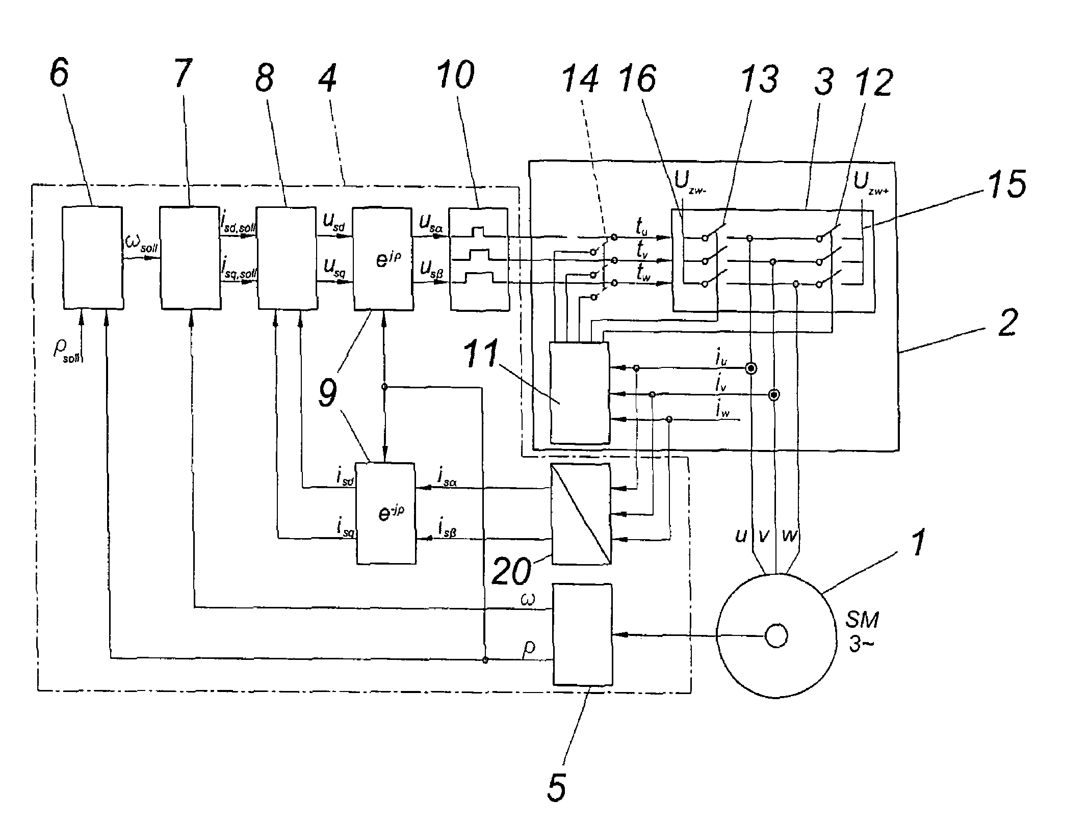
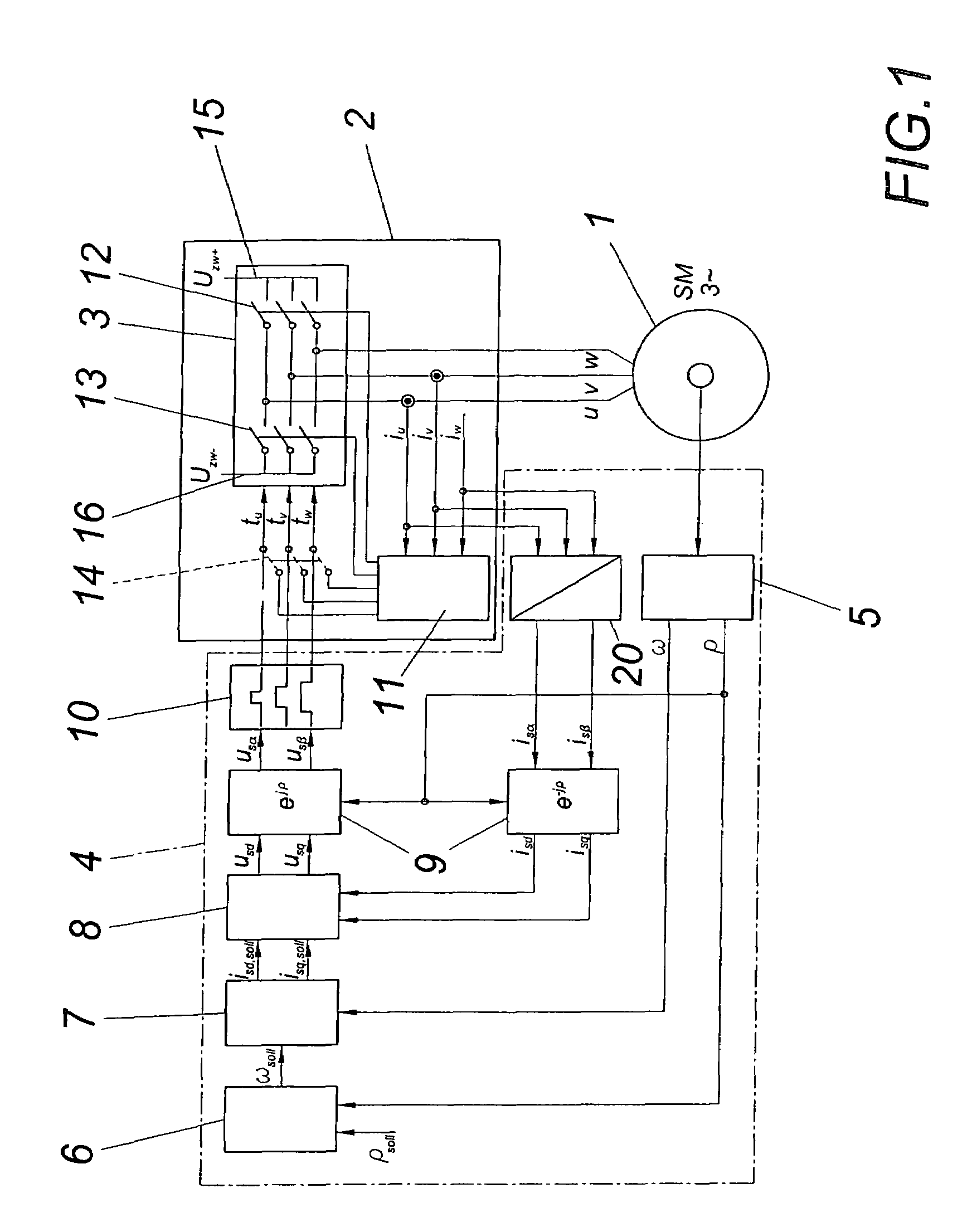
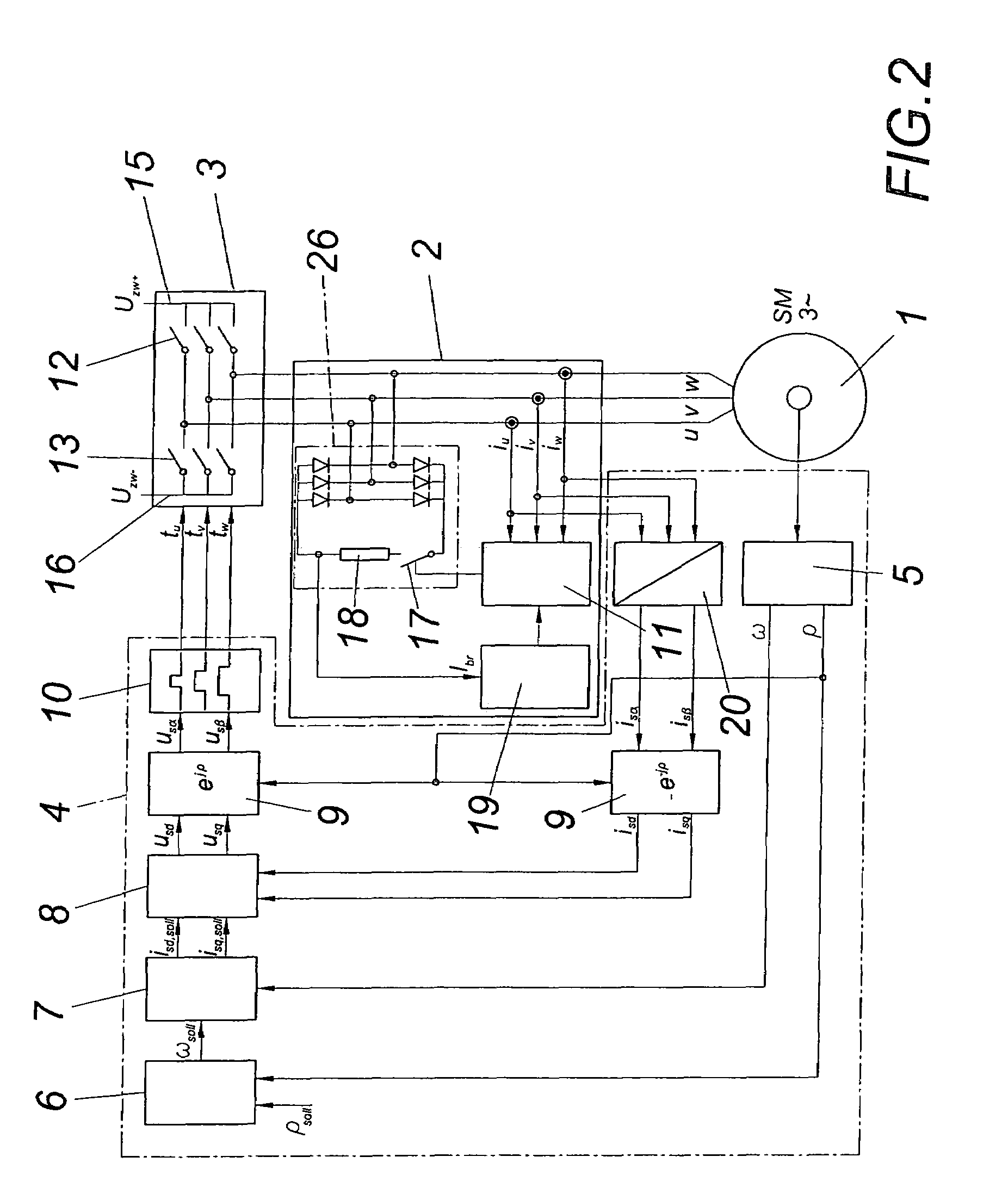
[0016]A permanent-field synchronous machine 1 comprises armature windings u, v, w which can be shorted via a braking device 2. A power converter 3 is provided for the normal operation of the synchronous machine 1, which converter is triggered by way of a triggering unit 4 in the usual manner.

[0017]The triggering unit 4 comprises, among other things, a rotational angle and rotational speed transducer 5, a positional controller 6, a speed controller 7, a current controller 8 and converters for mathematical transformations 9, a space vector modulation 10 and a two of three converter 20.

[0018]According to the embodiment according to FIG. 1, the braking device 2 comprises a torque controller 11 which shorts the power breaker elements 12 and 13 in a preferably alternating manner in the case of a braking. Prior to this, it is necessary to prevent a triggering of the power breakers 12 and 13 by the triggering unit 4, for which purpose the switches 14 are opened in this case. For the purpose...


PUM


Abstract

A method is proposed for braking a synchronous machine 1, with the armature windings (u, v, w) of the synchronous machine 1 being short-circuited, optionally by interposing at least one braking resistor. In order to keep the braking moment constant over virtually the entire speed range it is proposed that the short-circuit current is regulated by a pulse-width modulation depending on the difference between the setpoint value of the short-circuit current corresponding to the setpoint value of the braking moment and the actual value of the short-circuit current.

Description

CROSS REFERENCE TO RELATED APPLICATIONS[0001]Applicants claim priority under 35 U.S.C. §119 of Austrian Application No. A 1834 / 2003 filed Nov. 14, 2003. Applicants also claim priority under 35 U.S.C. §365 of PCT / AT / 2004 / 000401 filed Nov. 12, 2004. The international application under PCT article 21(2) was not published in English.FIELD OF THE INVENTION [0002]The invention relates to a method for braking a synchronous machine, with the armature windings of the synchronous machine being short-circuited, optionally by interposing at least one braking resistor.DESCRIPTION OF THE PRIOR ART [0003]A synchronous machine is further proposed for performing the method with a permanent-field rotor for example and with a shortable armature winding which is connected to a power converter which comprises a half bridge each for positive and negative half-waves of the current, which half bridge can be switched via a power breaker.[0004]In the case of overload, mains voltage failure, intermediate circ...

Claims


Application Information

Patent Timeline
Patent Type & Authority Patents(United States)
IPC IPC(8): H02P3/22H02P6/24H02P21/00H02P23/00
CPCH02P3/22H02P6/24H02P21/0092H02P23/0063H02P21/36H02P23/20
Inventor RAINER, JOSEFBERNECKER, ERWIN
Owner B&R IND AUTOMATION GMBH
Why Eureka
Try Eureka