Receiver

a receiver and superheterodyne technology, applied in the field of receivers, can solve the problems of increasing the cost of receivers, large characteristics of temperature and time, and inability to perform check, so as to avoid influence and interference and stable reception

Inactive Publication Date: 2008-05-13
SONY CORP
View PDF2 Cites 20 Cited by
  • Summary
  • Abstract
  • Description
  • Claims
  • Application Information

AI Technical Summary

Benefits of technology

[0012]According to one embodiment of the present invention, selectivity characteristics of the receiver can be subjected to self test and stable reception is possible even if the intermediate frequency filter is fabricated to be in one chip monolithic IC. The image characteristics can also be tested, and self test is possible also for reception circuits of the low IF scheme and direct conversion scheme. Initial adjustment and test of the reception circuit can be performed by using the same system. Various characteristics can be checked or adjusted easily.
[0013]If the external antenna is connected during the self test, an alarm is issued and the test signal is not formed. The test signal will not be irradiated inadvertently as radio waves from the external antenna. It is also possible to avoid influence and interference upon the self test due to a reception signal of broadcasting waves.

Problems solved by technology

Therefore, if a test signal generator is built in the receiver, the receiver cost increases.
If an intermediate frequency filter together with a reception circuit is fabricated in IC, although a change in the characteristics with temperature and time is large, check is not performed.
However, many test signal generators of a simple type cannot form the test signal having the image frequency.

Method used


Image

  • Receiver
  • Receiver
  • Receiver

Examples


Embodiment Construction

[0018][1] Reception Circuit 10

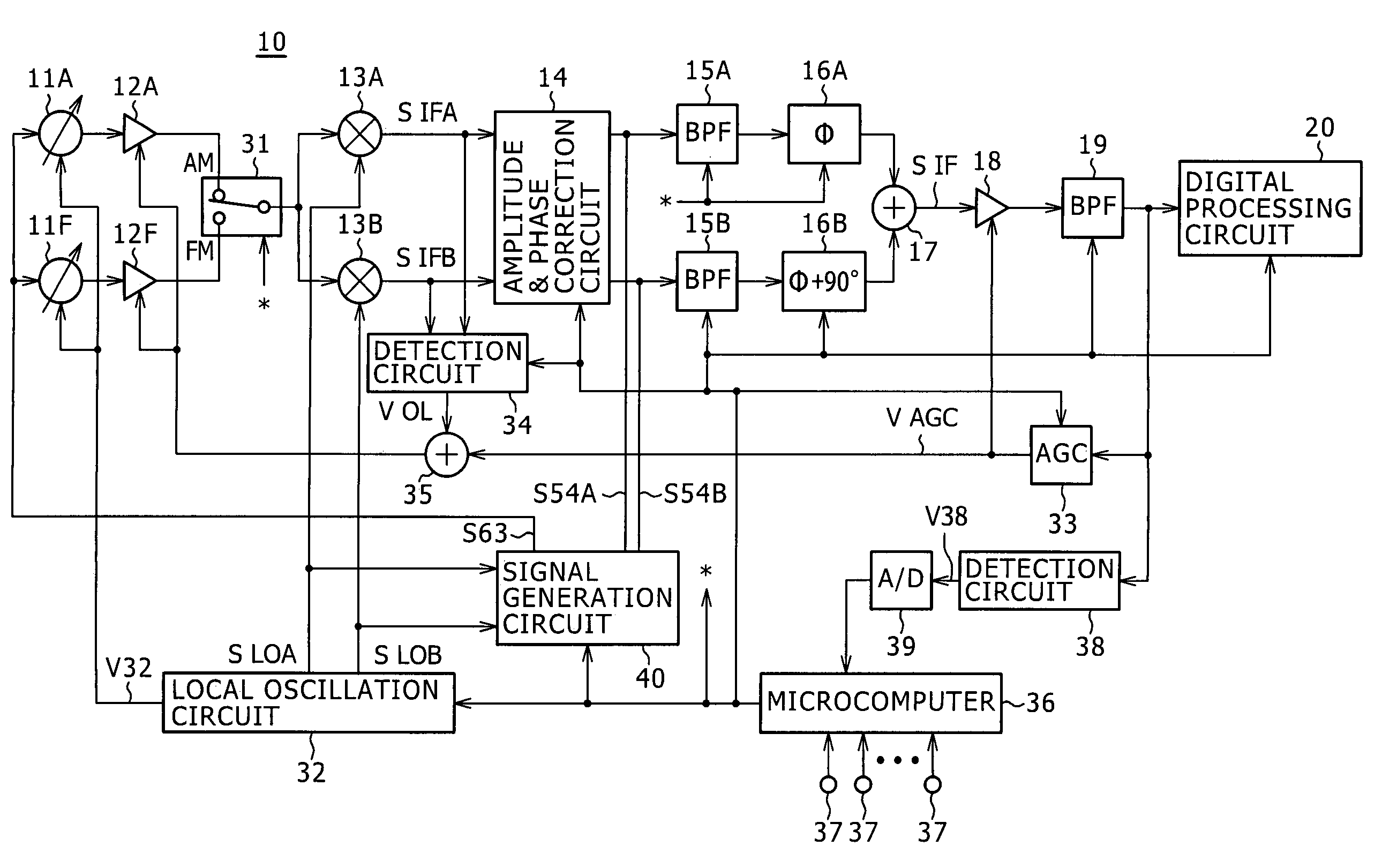
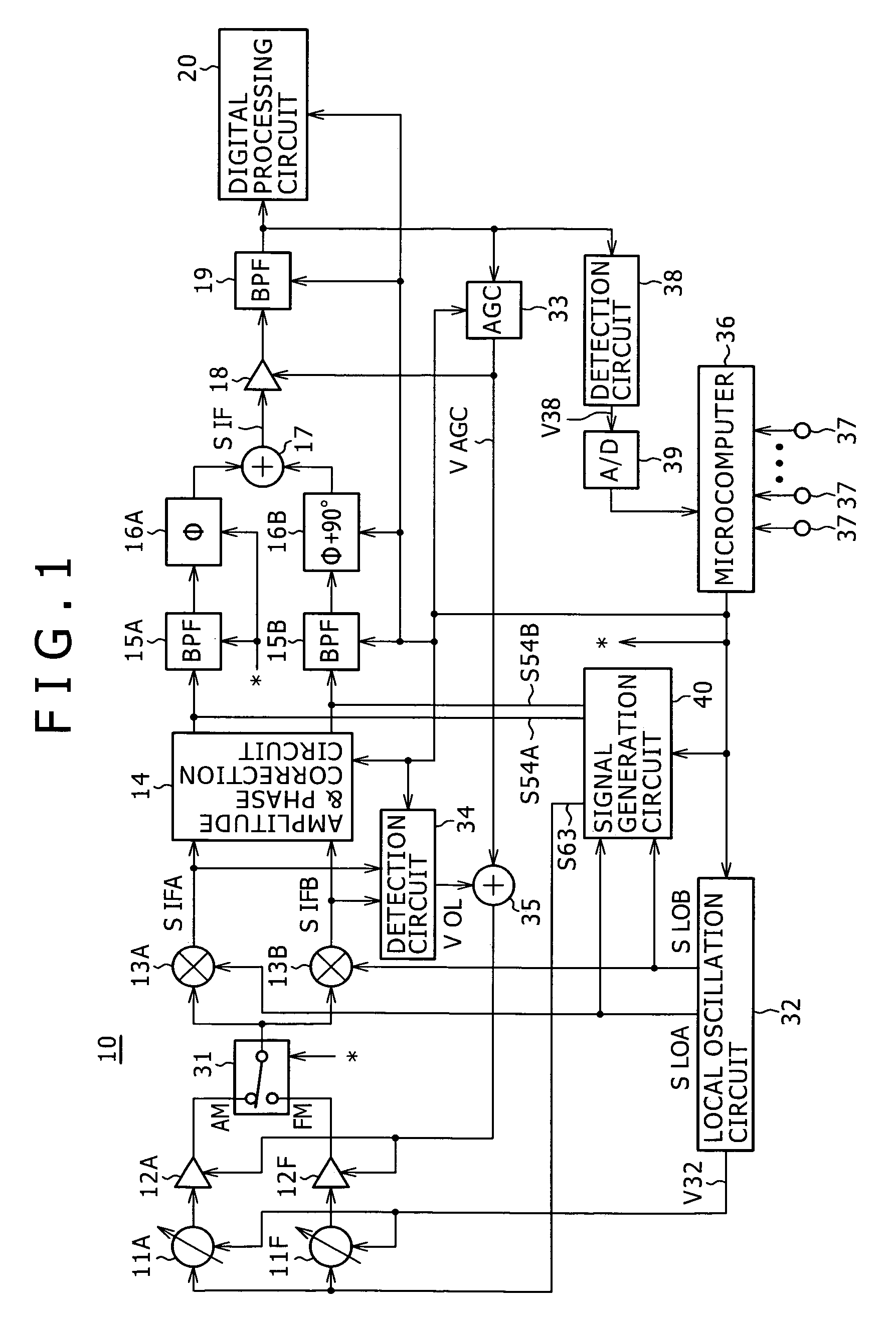
[0019]FIG. 1 is a block diagram showing an example of a reception circuit 10 of a receiver for AM broadcasting (middle wave broadcasting) and FM broadcasting to which the present invention is applied. This reception circuit 10 is of a so-called low IF scheme in which an intermediate frequency is set to be much lower frequency than a reception frequency by setting a local oscillation frequency near to the reception frequency. A reception signal is frequency-converted into a pair of orthogonal intermediate frequency signals, and the image characteristics are improved by phase processing.

[0020]Namely, during AM broadcasting reception, a reception signal SRX having a desired frequency (target reception frequency) fRX is picked up from an antenna tuning circuit 11A of an electronic tuning type, and this reception signal SRX is supplied to a pair of mixer circuits 13A and 13B via a high frequency amplifier 12A and a band switching circuit 31.

[0021]During FM b...


PUM


Abstract

A receiver includes a tuning circuit for picking up a reception signal having a desired frequency, a local oscillator for forming an oscillation signal, a first mixer for frequency-converting the reception signal into an IF signal by using the oscillation signal, an IF filter for deriving the IF signal from an output signal of the first mixer, a signal forming circuit for forming an AC signal having a frequency equal to a frequency of the IF signal, a second mixer to be supplied with the AC signal and the oscillation signal, a deriving circuit for deriving a signal having a desired frequency or an image frequency from an output of the second mixer, and a detector for detecting a level of the IF signal, wherein a self test is performed by supplying the signal derived from the deriving circuit to the tuning circuit and checking a detection output level of the detector.

Description

CROSS REFERENCES TO RELATED APPLICATIONS[0001]The present invention contains subject matter related to Japanese Patent Application JP 2004-116498 filed in the Japanese Patent Office on Apr. 12, 2004, the entire contents of which being incorporated herein by reference.BACKGROUND OF THE INVENTION[0002]1. Field of the Invention[0003]The present invention relates to a receiver of a super-heterodyne system.[0004]2. Description of Related Art[0005]In a receiver of a super-heterodyne system, the reception characteristics such as a reception sensitivity and image interference characteristics are degraded if the rated frequency relation between a reception frequency, a local oscillation frequency and an intermediate frequency is shifted.[0006]A test signal generator is therefore provided for checking and adjusting the reception sensitivity, the center frequencies of an antenna tuning circuit and an intermediate frequency filter, and the reception characteristics such as image interference ch...

Claims


Application Information

Patent Timeline
Patent Type & Authority Patents(United States)
IPC IPC(8): H04B17/00H04B1/26H03J1/00H04B1/06H04B1/10H04B1/28H04B1/30H04N5/14H04N9/64H04N11/02H04N17/04
CPCH03J1/0008H04B1/28H04N5/4446H04N17/045H02J7/0044
Inventor OKANOBU, TAIWA
Owner SONY CORP
Why Eureka
Try Eureka