Corn head row unit

a corn head and row unit technology, applied in the field of corn harvesting machinery, can solve the problems of the speed at which the corn ears are damaged, and achieve the effects of improving the performance of the corn head, reducing congestion mote levels, and improving material flow

Inactive Publication Date: 2008-05-20
CALMER MARION
View PDF30 Cites 74 Cited by
  • Summary
  • Abstract
  • Description
  • Claims
  • Application Information

AI Technical Summary

Benefits of technology

[0016]The present invention contains an ear separation chamber which is the area between the row unit covers and above the stripper plates and extends through all the zones. It designates at least four (4) interrelated overlapping zones with separate functions and purposes within each row unit. The combination of zones, relationships and sub-functions improves the performance of the corn head and combine by allowing better material flow through the row unit, reducing congestion mote levels through the row unit, conveying systems and the combine, thereby improving combine speeds and efficiencies. The four (4) current interrelated overlapping zones are the Alignment, Entry, Ear Separation and Post-Ear Separation Plant Ejection Zones.

Problems solved by technology

However, the maximum vertical stalk speed before ear separation is the speed at which the ears of corn are damaged within the row unit.

Method used


Image

  • Corn head row unit
  • Corn head row unit
  • Corn head row unit

Examples


Embodiment Construction

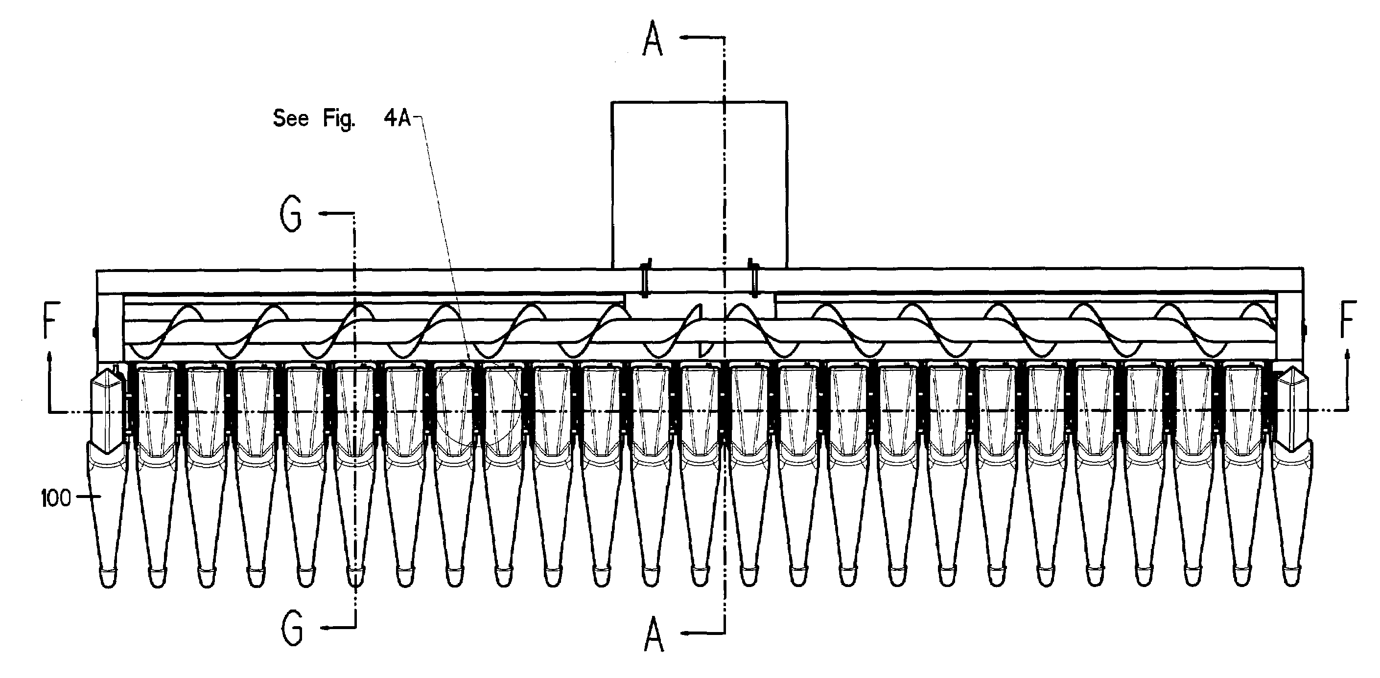
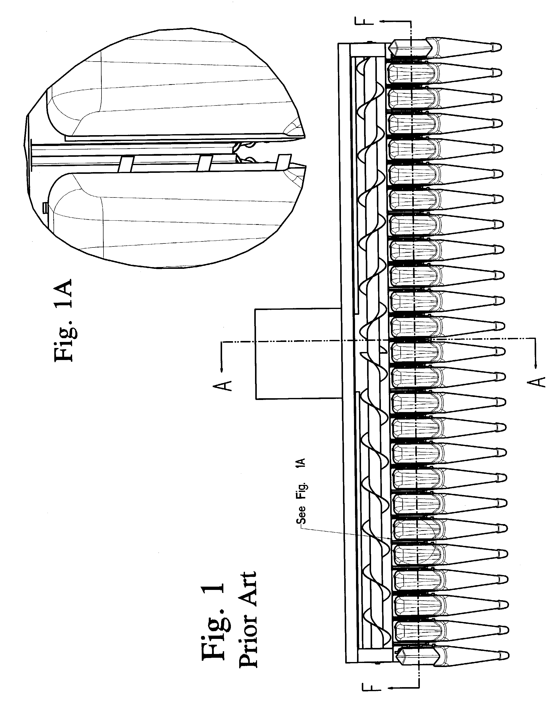
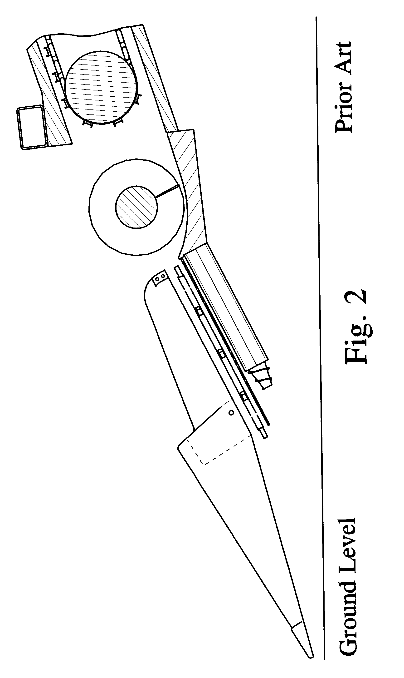
[0041]The operation of corn heads incorporating this invention in FIGS. 4 through 11 are similar to that of the operation of corn heads of the prior art as illustrated in FIGS. 1, 2, &3. The power to drive this corn head row unit is provided from a main drive shaft through a gearbox as described in the prior art. In FIGS. 4, 5, &11 the corn stalks are lifted and guided toward the row unit by dividers 100. In FIGS. 4A, 5, &11 rotating gathering chain 120 contains enlarged gathering paddles 110 and directs the corn plants toward the ear separation chamber 140.

[0042]In FIGS. 4A & 6 the corn plants are further centered into the ear separation chamber 140 by improved stripper plates 130.

[0043]In FIG. 4A enlarged gathering chain paddles 110 have an increased angle relative to the gathering chain 120 which makes them more aggressive when gathering down corn plants.

[0044]In FIG. 5 when harvesting down corn some corn plants are severed or broken as the row dividers 100 and row unit cover 150...


PUM


Abstract

This row unit utilizes an improved multi-zone, multi-functional stalk roll, which contains a novel revolving entry window to improve entry and increase engagement of the fluted portion of the stalk roll flutes with the corn stalk. The stalk rolls described are multi-sectional and contain multi-length variable flutes. The number of flutes described for each zone may vary as well as whether the flutes are meshing or non-meshing and angled or non-angled. The stalk rolls described allow a constant speed drive shaft to create lower and/or higher effective circumferential contact speeds within each zone of the stalk roll. The invention provides that the rotating transport vanes located on the helical nose cone at the entry area to the stalk roll flutes lock the corn stalk into a revolving entry window. This novel row unit contains a multi-zone, multi-functional stripper plate that ensures minimal ear wedging and maximum discharge of material other than ears. This row unit utilizes a novel gathering/conveying chain(s), which reduces the number of and increases the angle and size of the paddles. This row unit design optimizes operation between the components imparting force to the corn plant and ears. The invention has a smooth uninterrupted improved flow of corn stalk material through the ear separation chamber and is the first row unit designed to be environmentally friendly by ensuring that the majority of the corn plant remains connected to its original root system which prevents it from rapidly decomposing, blowing or washing away. The row unit cover is spatially designed for improved flow in down, damp and tough harvesting conditions.

Description

PRIORITY[0001]Applicant states that that this utility patent application claims priority from the provisional patent application specification filed on Mar. 15, 2002 and given Ser. No. 60 / 364813 by the United States Patent and Trademark Office.FIELD OF THE INVENTION[0002]This invention relates to corn harvesting machinery, specifically the corn picking row unit of the corn head. The corn head contains several row units. Each row unit contains a row crop divider, a row unit hood, gathering / conveying chain(s), two stripper plates, two stalk rolls, a row unit frame, and a gearbox. The gearbox powers the row unit for gathering corn plants then stripping, separating and conveying ears of corn from the corn plant.BACKGROUND OF THE INVENTION[0003]As shown in FIG. 1, corn heads are provided with several row crop dividers for retrieving, lifting, and directing the rows of corn stalks toward their respective ear separation chambers.[0004]As shown in FIG. 2, these crop dividers in combination ...

Claims


Application Information

Patent Timeline
Patent Type & Authority Patents(United States)
IPC IPC(8): A01D45/02
CPCA01D45/025
Inventor CALMER, MARION
Owner CALMER MARION
Why Eureka
Try Eureka