Papermaking screen

a papermaking screen and fabric technology, applied in the field of papermaking screens, can solve the problems of undesirable marks in paper, unsuitable known approaches, and rapid change of longitudinal deflection of the fabric of the screen, and achieve the effects of high stiffness values, high cross-directional stability, and preventing paper marks

Active Publication Date: 2008-05-20
ANDRITZ TECH & ASSET MANAGEMENT
View PDF19 Cites 9 Cited by
  • Summary
  • Abstract
  • Description
  • Claims
  • Application Information

AI Technical Summary

Benefits of technology

[0010]Objects of the present invention are to provide a papermaking screen characterized by high stiffness values, in particular a high degree of cross-directional stability, and affording dewatering output comparable to that of the disclosed solutions and helping prevent formation of marks in the paper.

Problems solved by technology

This use results in rapidly changing deflection of the fabric of the screens in the longitudinal direction.
However, the known approaches are now unsuitable if it is desired to employ different warp diameters on the machine and paper sides.
In a practical application, this leads to some extent to undesirable marks in the paper.
To counter this result, the binder yarns are made to be increasingly thinner, but this has the disadvantage that the service life of the connection of individual fabric layers is correspondingly shortened.
In addition, practical application has shown that “looping through” of the binding weft yarns may occur, this resulting in separation of the individual layers and rendering the fabric unusable.
Despite the good interconnection of the two individual fabrics, the disclosed solutions present the essential disadvantage that the upper warp of the paper side is not supported at the points of intersection of the binding wefts.
This disadvantage of absence of support arises especially when upper weft and binding pair are introduced in alternating sequence, so that, for example, a complete upper weft follows a binding pair which is then followed by an upper weft.
This arrangement leads to uneven progress of the fabric on the paper side, something which may result in undesirable marks in the paper.

Method used


Image

  • Papermaking screen
  • Papermaking screen
  • Papermaking screen

Examples


Embodiment Construction

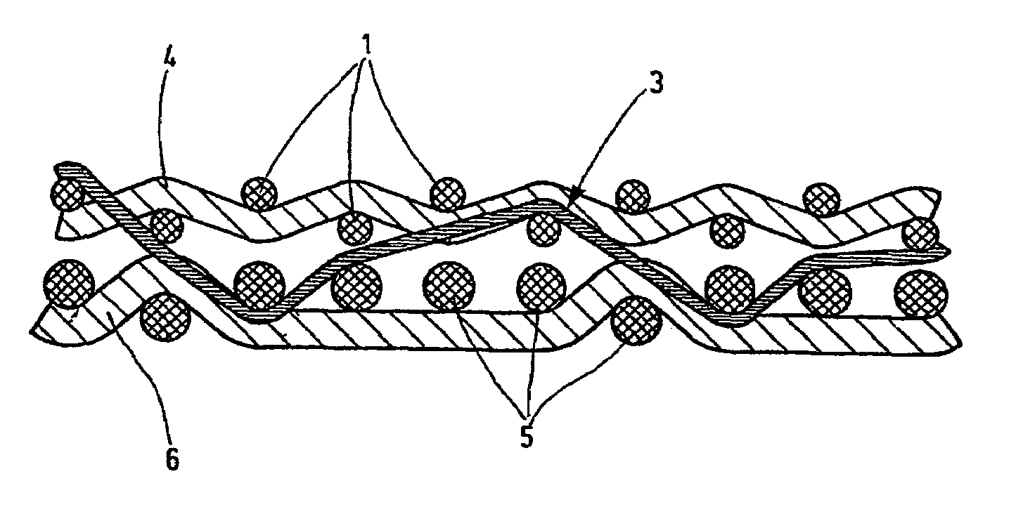
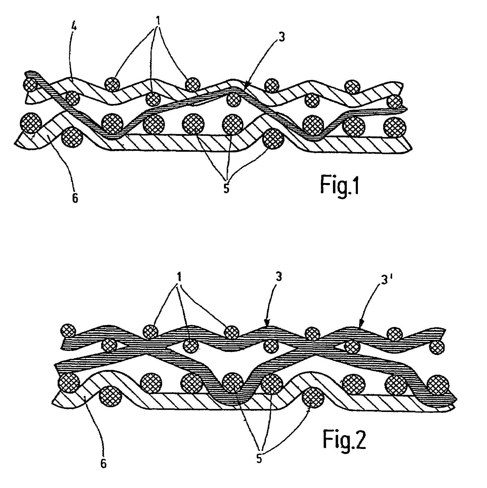
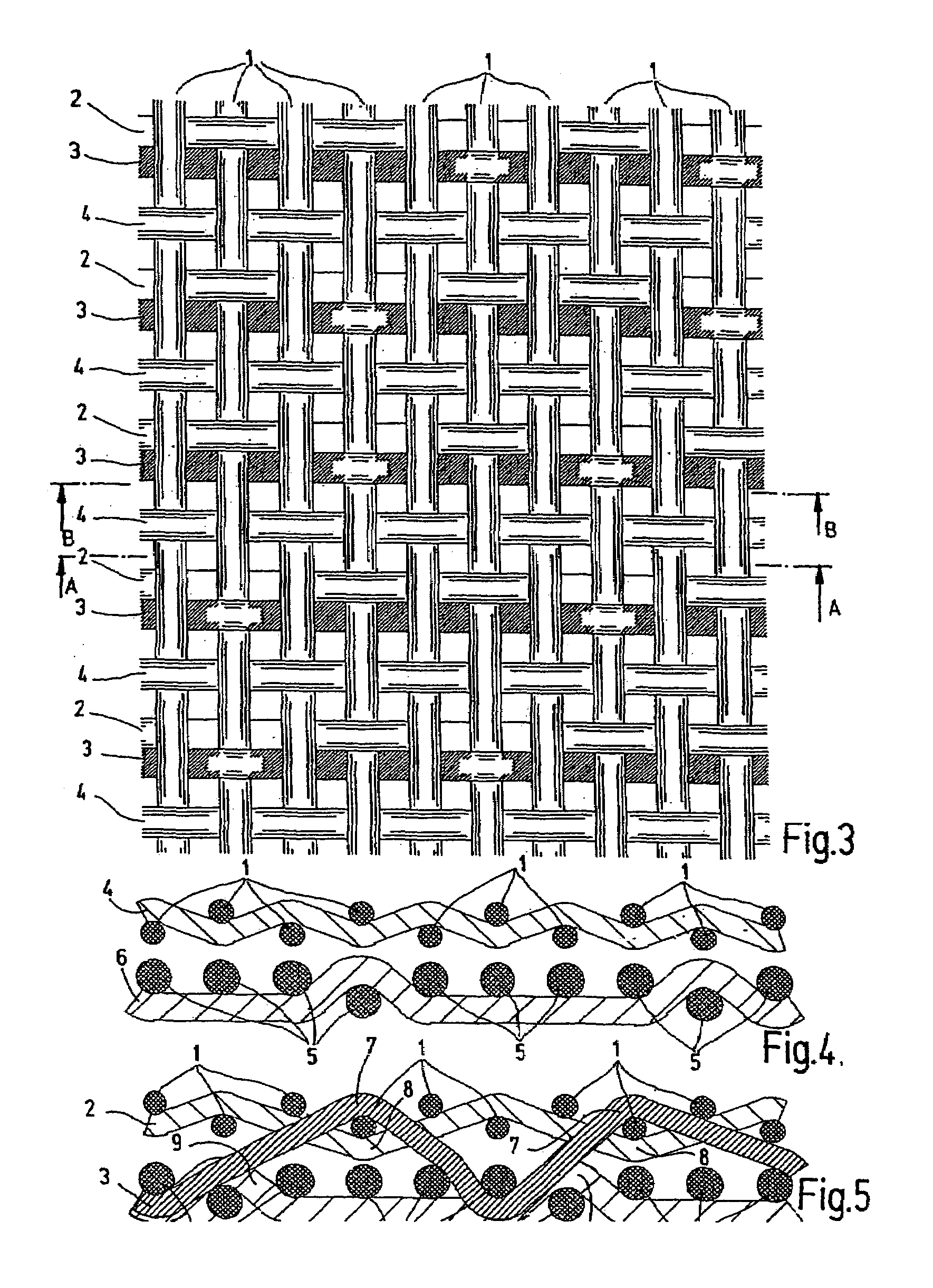
[0024]The following numeral identifications are employed in all the illustrations:[0025]1 upper warp[0026]2 upper weft (with binding weft)[0027]3′3 binding weft[0028]4 upper weft[0029]5 lower warp[0030]6 lower weft[0031]7 extension above[0032]8 extension below[0033]9 extension above through lower weft 6

[0034]In FIG. 1, the conventional papermaking screen, as viewed in FIG. 1, has two individual fabrics, the upper individual fabric or upper fabric forming the paper side and the individual fabric positioned below it representing the bottom side or lower fabric. The upper individual fabric is formed of a set of weft yarns 2 as upper weft yarns and warp yarns 1 as upper warp yarns. The machine side located underneath also has a set of weft yarns 6 as lower weft yarns and warp yarns 5 as lower warp yarns. The disclosed screen has a linen bond as the binding type for the paper side. The lower fabric is configured as a five-shank fabric with respect to a repeat. As FIG. 1 shows, the two in...


PUM

PropertyMeasurementUnit
speedsaaaaaaaaaa
diametersaaaaaaaaaa
cross-directional stabilityaaaaaaaaaa

Abstract

A papermaking screen includes at least one individual fabric for the paper side and at least one individual fabric for the machine side. Each of those fabrics is provided with a set of weft yarns (4, 6) and warp yarns (1, 5). At least one part of the superimposed individual fabrics is interconnected via binder yarns (3). The two fabric layers (paper side and machine side) are connected by binder yarns that are fully integrated into the fabric structure of the paper side and are able to support the resulting binding point due to each binder yarn (3) engaging with warp yarns (1) of the individual fabric from above at defined points on the paper side, while at least one weft yarn (2) of the individual fabric engages with the warp yarns (1) from below on the opposite side so as to lean against it such that the binder yarns remain on one plane along with the weft and the remaining warp yarns. This arrangement results in a high-strength papermaking screen which has very good dewatering power and a regular structure.

Description

FIELD OF THE INVENTION[0001]The present invention relates to a papermaking screen having at least one single fabric for the paper side and at least one single fabric for the machine side. Each fabric has a set of weft yarns and warp yarns. At least a part of the stacked individual fabrics are connected to each other by binder yarns.BACKGROUND OF THE INVENTION[0002]Use is increasingly made today in the papermaking industry of high-performance papermaking machines running at speeds of up to 2000 m / min and with operating widths exceeding 10 m. As a very general rule, the sheet forming unit is configured as a twin-wire former, in many instances as a gap former. In typical machines, the sheet forming process takes place immediately in a relatively short dewatering zone between two papermaking screens. The time for sheet formation is reduced to a few milliseconds because of this short distance and the high output rate. The solid content or dry content of the fiber suspension must be raise...

Claims


Application Information

Patent Timeline
Patent Type & Authority Patents(United States)
IPC IPC(8): D21F1/10D21F7/08D03D25/00D21F1/00
CPCD21F1/0045Y10S162/903Y10S162/90
Inventor HEGER, WOLFGANGFICHTER, KLAUS
Owner ANDRITZ TECH & ASSET MANAGEMENT
Why Eureka
Try Eureka