Roller conveyor

a conveyor and roller technology, applied in the direction of roller-ways, transportation and packaging, etc., can solve the problems of high operating voltage, high cost, high loss factor, and associated costs, and achieve the effect of costing less to manufacture and opera

Active Publication Date: 2008-05-20
EISENMANN AG
View PDF14 Cites 8 Cited by
  • Summary
  • Abstract
  • Description
  • Claims
  • Application Information

AI Technical Summary

Benefits of technology

[0010]The concept according to the present invention of a roller conveyor not only avoids cumbersome belt drives or other transmission mechanisms by associating a separate drive motor with each driven roller. The use of a plurality of drive motors, which each individually have a relatively low power consumption, moreover opens up the possibility of using low voltage motors without the current that is to be supplied to each drive motor becoming excessively high. Since low operating voltages do not call for such stringent safety measures, cost benefits accrue. Semiconductor components, to which only low operating voltages are applied, moreover have smaller losses and therefore also require less cooling. Finally, the printed-circuit boards, on which the control circuits are assembled, may be equipped with smaller interspaces between conductors, thereby reducing the size of these printed-circuit boards and making it easier to integrate these printed-circuit boards e.g. directly with the drive motors in a sub-assembly.

Problems solved by technology

The voltage used to operate the drive motors is identical to the system voltage that is available in each case and is therefore generally between approximately 200 V and approximately 600 V. Because of the relatively high operating voltage it is necessary to take considerable safety measures, this being associated with costs.
Costs are further increased by the fact that the semiconductor components, to which the high operating voltage is to be applied, are relatively expensive and have a relatively high loss factor.

Method used


Image

  • Roller conveyor
  • Roller conveyor
  • Roller conveyor

Examples


Embodiment Construction

[0018]While this invention is susceptible of embodiment in many different forms, there is shown in the drawings and will herein be described in detail one or more embodiments with the understanding that the present disclosure is to be considered as an exemplification of the principles of the invention and is not intended to limit the invention to the embodiments illustrated.

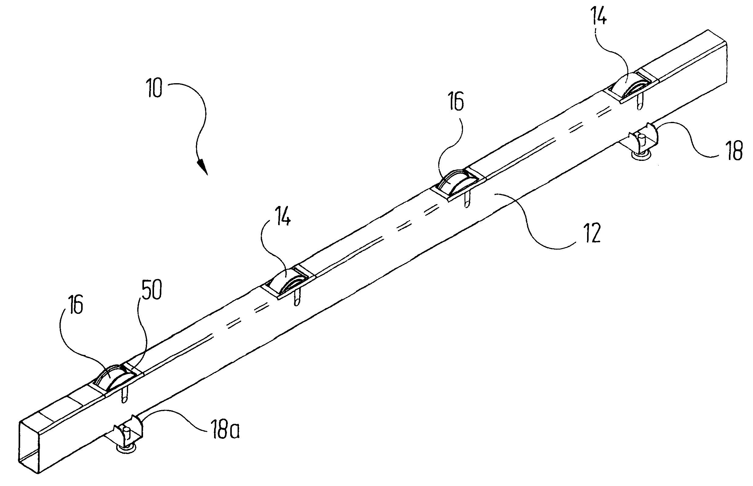
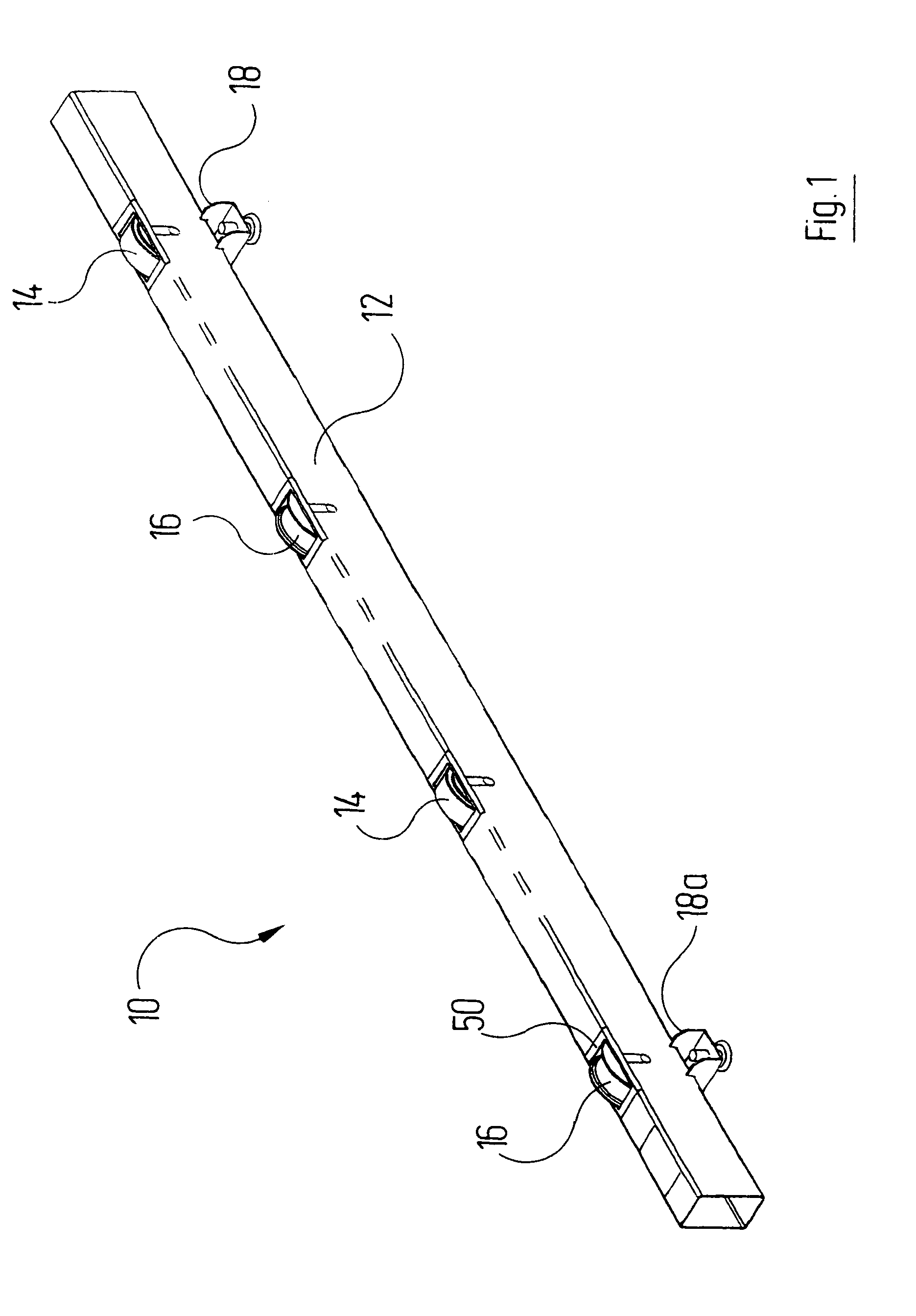
[0019]Reference is made first to FIG. 1, which shows a perspective view of a roller rail that is denoted as a whole by the reference character 10. The roller rail 10 comprises a longitudinal beam 12, which takes the form of a hollow section with a rectangular cross section. In the longitudinal beam 12 two driven rollers 14 and two non-driven rollers 16 are arranged alternately in longitudinal direction. The driven rollers 14 are unprofiled and carry a high-friction coating. The non-driven rollers 16 have a profile with wheel flanges on both sides. The wheel flanges effect lateral guidance of the runners of the sk...


PUM


Abstract

A roller conveyor including a plurality of driven rollers disposed in two parallel tracks. With each driven roller a separate drive motor is associated, which takes the form of a low voltage motor. The drive motors are supplied from at least one low voltage source. They are preferably hub motors, which are operated with direct current. By virtue of the low voltage technology, less expensive components may be used and the safety requirements may be reduced.

Description

RELATED APPLICATIONS[0001]The present invention claims the benefit of the filing date of German Patent Application, Serial No. 10 2006 005 983.2, filed Feb. 8, 2006; the content of which is incorporated by reference herein.[0002]This application also relates to concurrently filed U.S. patent application Ser. Nos. 11 / 701,175, entitled ROLLER CONVEYOR; and, 11 / 701,176, entitled SET OF ROLLER CONVEYORS.TECHNICAL FIELD[0003]The invention relates to a roller conveyor comprising a plurality of driven rollers disposed in two parallel tracks; a plurality of drive motors for driving the rollers; and, at least one voltage source, from which the drive motors are supplied.BACKGROUND OF THE INVENTION[0004]Roller conveyors are used to transport goods carriers such as e.g. pallets. In the automobile industry they are often used to transfer vehicle bodies or parts of vehicle bodies between individual processing stations. The vehicle bodies are in said case fastened on so-called skids. This term is ...

Claims


Application Information

Patent Timeline
Patent Type & Authority Patents(United States)
IPC IPC(8): B65G13/06
CPCB65G13/06
Inventor DINGLER, GUENTHERSWOBODA, WERNERGROSS, ERWIN
Owner EISENMANN AG
Why Eureka
Try Eureka