System for bi-directionally controlling the cryo-tip of a cryoablation catheter

a cryoablation catheter and bi-directional control technology, applied in the field of bi-directional control systems, can solve the problems of retraction of the second pull wire not necessarily operating to smoothly recover the deflection and straighten the tip, and the recovery of relatively large deflections is smooth

Inactive Publication Date: 2008-05-20
CRYOCOR
View PDF62 Cites 27 Cited by
  • Summary
  • Abstract
  • Description
  • Claims
  • Application Information

AI Technical Summary

Benefits of technology

[0011]In addition to the CW and CCW reels, the system further includes a drive cog that is mounted on the handle housing for rotation about the axis of rotation in either a first or second rotation direction. Functionally, when the drive cog is rotated in the first rotation direction, it engages and rotates the CW reel. On the other hand, when the drive cog is rotated in the second rotation direction, it engages and rotates the CCW reel. Each of the reels and the drive cog are stacked along the rotation axis and are positioned inside the handle housing opposite a user operable turn knob. Specifically, the turn knob is positioned outside the handle housing with a friction washer interposed between the housing and the knob. With this combination, a screw can then be used to clamp the knob toward the drive cog at a preselected clamping pressure. As a consequence, the friction washer and the wall of the housing are sandwiched between the turn knob and drive cog. As intended for this structural arrangement, the user can rotate the turn knob to selectively pull on either the first or the second pull wires. Also, the friction washer then “locks” the knob in place after a preselected rotation. This allows the operator to release their hand from the knob while maintaining a preselected tip deflection.
[0013]In another aspect of the invention, the system includes a mechanism that is operable on the pull wires for delaying an application of tension on one of the pull wires until at least a portion of any tension on the other pull wire is released. This delay allows for the recovery of large deflections. For the case where CW and CCW reels and a drive cog are used to control the pull wires, the delay mechanism can be implemented by the establishment of a gap between the cog and the reels. Specifically, when the tube is in a relaxed state and there is no tension on either pull wire, the cog is centered between the two reels with a gap between the cog and the CW reel and an equal size gap between the cog and the CCW reel. With properly sized gaps, only one wire at a time can be placed in tension, resulting in the smooth recovery of relatively large deflections.

Problems solved by technology

Moreover, this manipulation typically must be performed within a relatively limited space (e.g. the left atrium).
For these conventional systems, a change in deflection from one direction to another can be problematic.
However, when the deflection of the distal tip in the first direction is relatively large (e.g. ninety to one hundred eighty degrees or more), retraction of the second pull wire does not necessarily operate to smoothly recover the deflection and straighten the tip.

Method used


Image

  • System for bi-directionally controlling the cryo-tip of a cryoablation catheter
  • System for bi-directionally controlling the cryo-tip of a cryoablation catheter
  • System for bi-directionally controlling the cryo-tip of a cryoablation catheter

Examples


Embodiment Construction

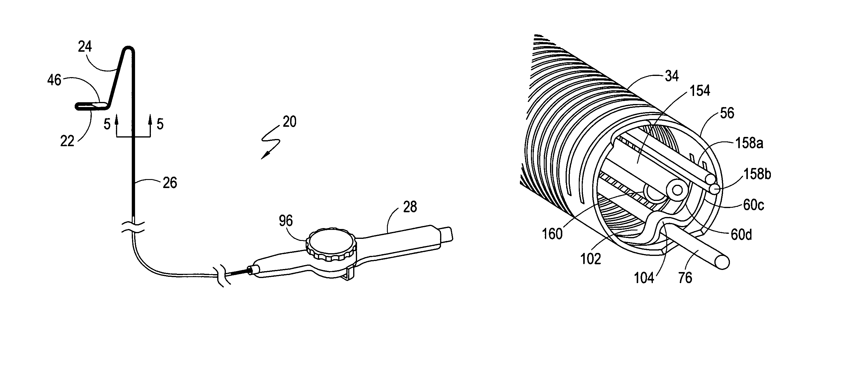
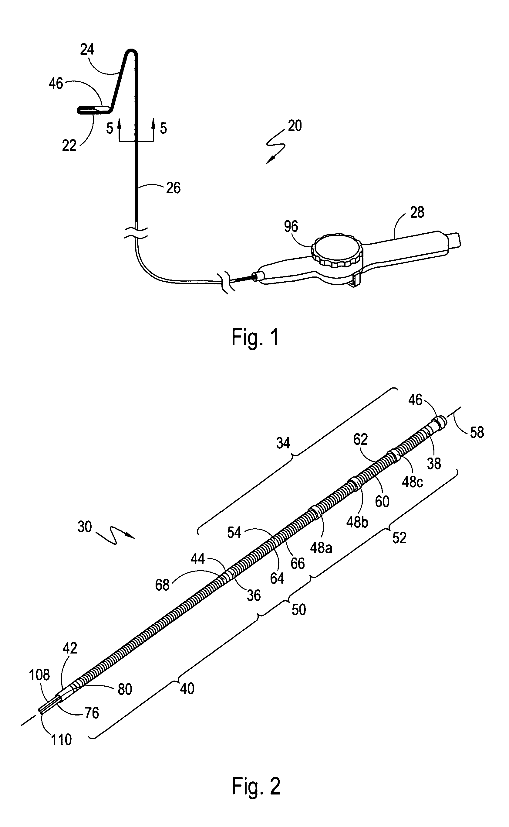
[0026]Referring initially to FIG. 1, a cryo-catheter for cryoablating a lesion in a body conduit of a patient is shown and generally designated 20. As indicated in FIG. 1, the cryo-catheter 20 can be manipulated into different configurations and orientations. To do this, the cryo-catheter 20 includes a system for deflecting a section 22 of the cryo-catheter 20 into a hoop configuration, as shown. It also includes a bi-directional control system for deflecting a section 24 of the cryo-catheter 20 in both a first direction and a second direction that is substantially coplanar and opposite the first direction. FIG. 1 further shows that the cryo-catheter 20 includes an elongated catheter body 26 that extends distally from a catheter handle 28. Although these deflecting systems are shown and disclosed herein as being part of a cryo-catheter 20, those skilled in the pertinent art will appreciate that these systems can be used as well in other types of catheters where bi-directional contro...


PUM


Abstract

A bi-directional system for actively deflecting the distal tip of a catheter includes a reconfigurable tube that is positioned proximal to the catheter's distal tip. The tube is formed with slits that are arranged to allow the tube to be transformed from a relaxed, cylindrical configuration to a plurality of deflected configurations. First and second pull wires are provided, with each wire having a respective distal end that is attached to the distal end of the tube. Each wire extends to a catheter handle where it is attached to a respective reel. The reels can be rotated, back and forth, to selectively deflect or relax the tube. To ensure a smooth recovery after a relatively large deflection, a mechanism is disclosed for delaying an application of tension on one of the pull wires until at least a portion of any tension on the other pull wire is released.

Description

FIELD OF THE INVENTION[0001]The present invention pertains generally to systems and methods for actively deflecting a distal portion of a catheter while the distal portion is positioned within a body conduit. More particularly, the present invention pertains to a bi-directional system for deflecting the distal portion of a catheter. The present invention is particularly, but not exclusively, useful as a system for bi-directionally controlling the cryo-tip of a cryoablation catheter.BACKGROUND OF THE INVENTION[0002]Atrial fibrillation is an irregular heart rhythm that adversely affects approximately 2.5 million people in the United States. It is believed that at least one-third of all atrial fibrillation originates near the ostium of the pulmonary veins. Anatomically, two pairs of pulmonary veins are connected to the left atrium of the heart with each pair delivering blood to the heart from one of the patient's lungs.[0003]It is further believed that the optimal technique to treat at...

Claims


Application Information

Patent Timeline
Patent Type & Authority Patents(United States)
IPC IPC(8): A61M31/00A61B17/00A61B18/02A61M37/00
CPCA61B18/02A61M25/0043A61M25/0136A61M25/0138A61M25/0147A61B2017/003A61B2018/0212A61B2018/0262A61M2025/0161
Inventor KOERNER, RICHARD J.LENTZ, DAVID J.O'DONNELL, JOSEPH A.SALINAS, ALVIN B.
Owner CRYOCOR
Why Eureka
Try Eureka