
Air separation system and method with modulated warning flow

a technology of air separation system and warning flow, applied in the field of air separation system and method, can solve the problems of increased fuel consumption, reduced engine performance, idle secondary asms, etc., and achieve the effect of improving the efficiency of secondary asms

Active Publication Date: 2008-05-20
PARKER INTANGIBLES LLC
View PDF10 Cites 49 Cited by
  • Summary
  • Abstract
  • Description
  • Claims
  • Application Information

AI Technical Summary

Benefits of technology

"The present invention provides an air separation system and method for aircraft inerting that improves efficiency of the secondary air separation module when high purity NEA flow is desired, such as during descent. The system includes a primary air separation module, a secondary air separation module, and a flow controller that provides a warming flow through the secondary air separation module to heat it up to above ambient temperature during a warming period. The system can deliver nitrogen-enriched air to the space to be inerted through the primary and supplemental downstream flows of nitrogen-enriched air during the high flow period, and the flow controller can control the flow through the main secondary outlet flow control valve and the main secondary inlet flow control valve to direct the flow to the space to be inerted or to the warming flow bypass line during the warming period. The invention provides an efficient and effective solution for aircraft inerting during descent."

Problems solved by technology

This use of engine bleed air can decrease engine performance and can lead to increased fuel consumption.
The secondary ASMs, however, are idle, i.e. shut off from the elevated temperature supply air, and can become thermally soaked at surrounding ambient bay temperatures considerably lower than the optimal operating temperature of the ASM.
Consequently, when the pressurized heated supply air is supplied to the secondary ASMs for high NEA flow during descent, initially the secondary ASMs will not be at the desired elevated temperature and thus will produce low purity NEA.

Method used


Image

  • Air separation system and method with modulated warning flow
  • Air separation system and method with modulated warning flow

Examples


Embodiment Construction

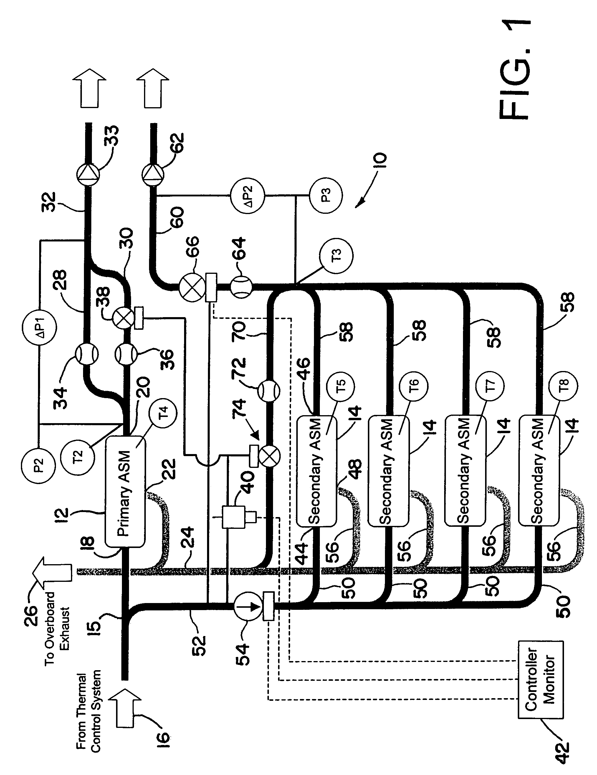
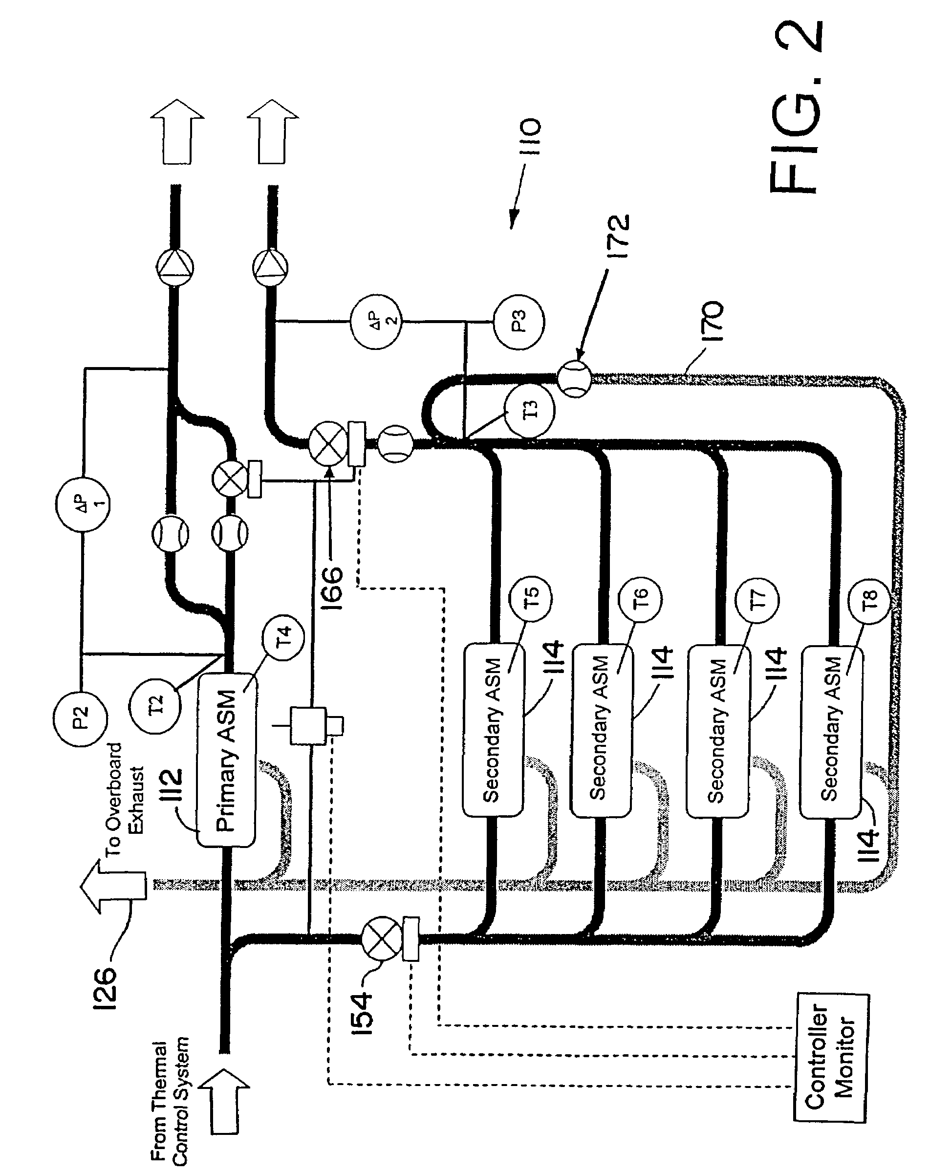
[0020]Referring now in detail to the drawings and initially to FIG. 1, an exemplary embodiment of an air separation system according to the invention is indicated generally by reference numeral 10. The illustrated system 10 is designed for use in an on-board inert gas generating system of an aircraft that supplies nitrogen-enriched air (NEA) to the fuel tank or tanks of an aircraft, and thus will chiefly be designed in this context. It will be appreciated, however, that the NEA can be used for inerting cargo holds and other void spaces in an aircraft. Moreover, the underlying principles of the invention have applicability to non-aircraft applications where a need exists for a supply of relatively inert, nitrogen-enriched air.

[0021]The system 10 generally comprises a primary air separation module 12 and one or more secondary air separation modules 14. Usually only one primary air separation module (ASM) will be utilized to produce nitrogen-enriched air (NEA) from a suitable supply so...


PUM

PropertyMeasurementUnit
temperatureaaaaaaaaaa
permeableaaaaaaaaaa
selectively permeableaaaaaaaaaa

Abstract

An inerting system and method characterized by a primary air separation module configured to communicate with an upstream source of pressurized air at elevated temperature for production of a primary downstream flow of nitrogen-enriched air to be delivered to a space to be inerted; a secondary air separation module configured to communicate with the upstream source of pressurized air at elevated temperature for production of a supplemental downstream flow of nitrogen-enriched air to be delivered to a space to be inerted when high nitrogen-enriched airflow is desired during a high flow period; and a flow controller configured to provide a warming flow through the secondary air separation module to heat the secondary air separation module to above ambient temperature during a warming period other than the high flow period.

Description

RELATED APPLICATION DATA[0001]This application claims the benefit of U.S. Provisional Application No. 60 / 503,813 filed Sep. 22, 2003, which is hereby incorporated herein in its entirety.FIELD OF THE INVENTION[0002]The invention herein described relates generally to air separation systems and methods and particularly those that supply nitrogen enriched air to spaces to be inerted, such as the ullage space in an aircraft fuel tank.BACKGROUND OF THE INVENTION[0003]Aircraft have used on-board inert gas generating systems (OBIGGS) to protect against fuel tank explosions by replacing the potentially explosive fuel vapor / air mixture above the fuel in the ullage space of the tanks with nitrogen-enriched air (NEA). The NEA is generated by separating oxygen from local, ambient air and pumping the inert, oxygen impoverished NEA into the tanks.[0004]Production of NEA typically is carried out by means of an apparatus relying on permeable membranes, or else on molecular sieves. The air separation...

Claims


Application Information

Patent Timeline
Patent Type & Authority Patents(United States)
IPC IPC(8): B01D53/04B01D53/22B64D37/00B65B1/04
CPCB01D53/0454B01D53/227B01D2256/10B01D2259/41B01D2259/4575B64D37/32
Inventor BONCHONSKY, MICHAEL J.DOW, STEVEN C.GOLLES, ROBERT F.JENSEN, BRYAN D.BONCHONSKY, MIKE
Owner PARKER INTANGIBLES LLC
Learn More