Supercharge Your Innovation With Domain-Expert AI Agents!

Gas flow panels integrated with solid oxide fuel cell stacks

a solid oxide fuel cell and gas flow panel technology, applied in the field of integrated solid oxide fuel cell systems and thermal management, can solve the problems of difficult to find suitable low-cost materials for sealing and interconnection for use at the operating temperature of solid oxide fuel cells, place stringent requirements on materials, etc., to reduce the operation of supplementary burners, reduce system airflow, and reduce the effect of oxidant inlet temperatures

Inactive Publication Date: 2008-05-20
GAS TECH INST
View PDF24 Cites 8 Cited by
  • Summary
  • Abstract
  • Description
  • Claims
  • Application Information

AI Technical Summary

Benefits of technology

This approach reduces system size and cost, increases efficiency, and extends stack life by smoothing temperature distributions, allowing for scalable and self-sustainable operation with reduced parasitic power consumption and heat loss.

Problems solved by technology

The high temperature of the solid oxide fuel cell, however, places stringent requirements on its materials.
Because of the high operating temperatures of conventional solid oxide fuel cells, the materials used in the cell components are limited by chemical stability in oxidizing and reducing environments, by chemical stability of contacting materials, by conductivity, and by thermo-mechanical compatibility.
However, as suggested above, it is difficult to find suitable low-cost materials for the sealant and interconnect for use at the solid oxide fuel cell operating temperature.
Effective heat integration between fuel cell stack heat removal and oxidant (air) preheating has been a major challenge for the solid oxide fuel cell.
Because the temperature gradient across the stack hardware is limited (usually less than about 100° C.
), the required cathode flow for the stack heat removal is very large.
This large air flow significantly increases the air preheater size.
The large size, in conjunction with the high air discharge temperature required, significantly increases the air preheater cost.
This is one major reason for the high cost of solid oxide fuel cell systems.
In addition, the large air flow increases the system pressure drop.
The combined effect of large flow and high pressure drop increases the air blower size and the auxiliary power consumption.
Consequently, the efficiency of the system is reduced.
This heat loss increases the difficulty of sustaining the stack temperature, may add to burner duty and lowers system efficiency.
Such high temperatures and high temperature gradients increase mechanical stress and accelerate deterioration of solid oxide fuel cell stacks.

Method used


Image

  • Gas flow panels integrated with solid oxide fuel cell stacks
  • Gas flow panels integrated with solid oxide fuel cell stacks
  • Gas flow panels integrated with solid oxide fuel cell stacks

Examples


Embodiment Construction

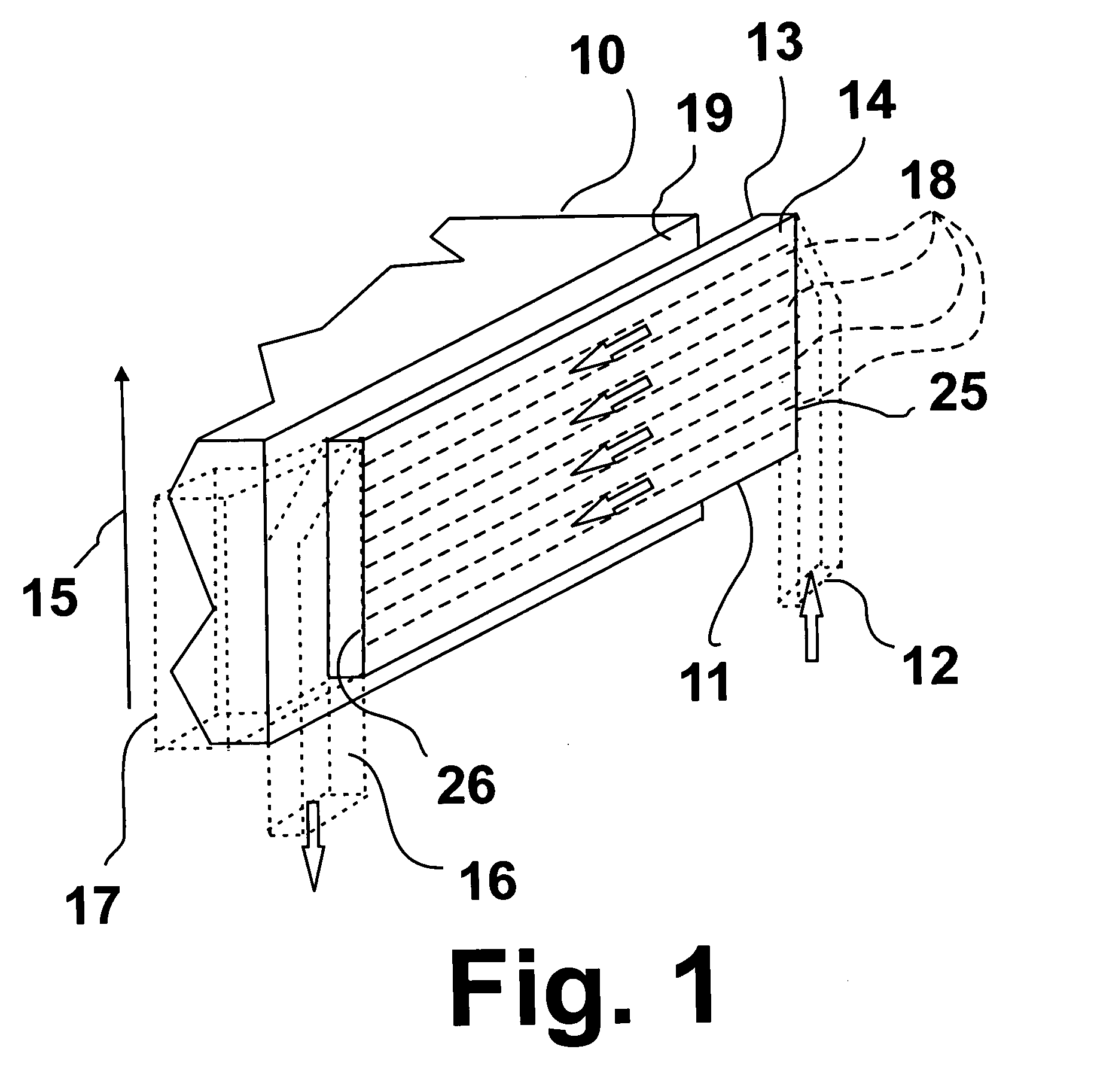
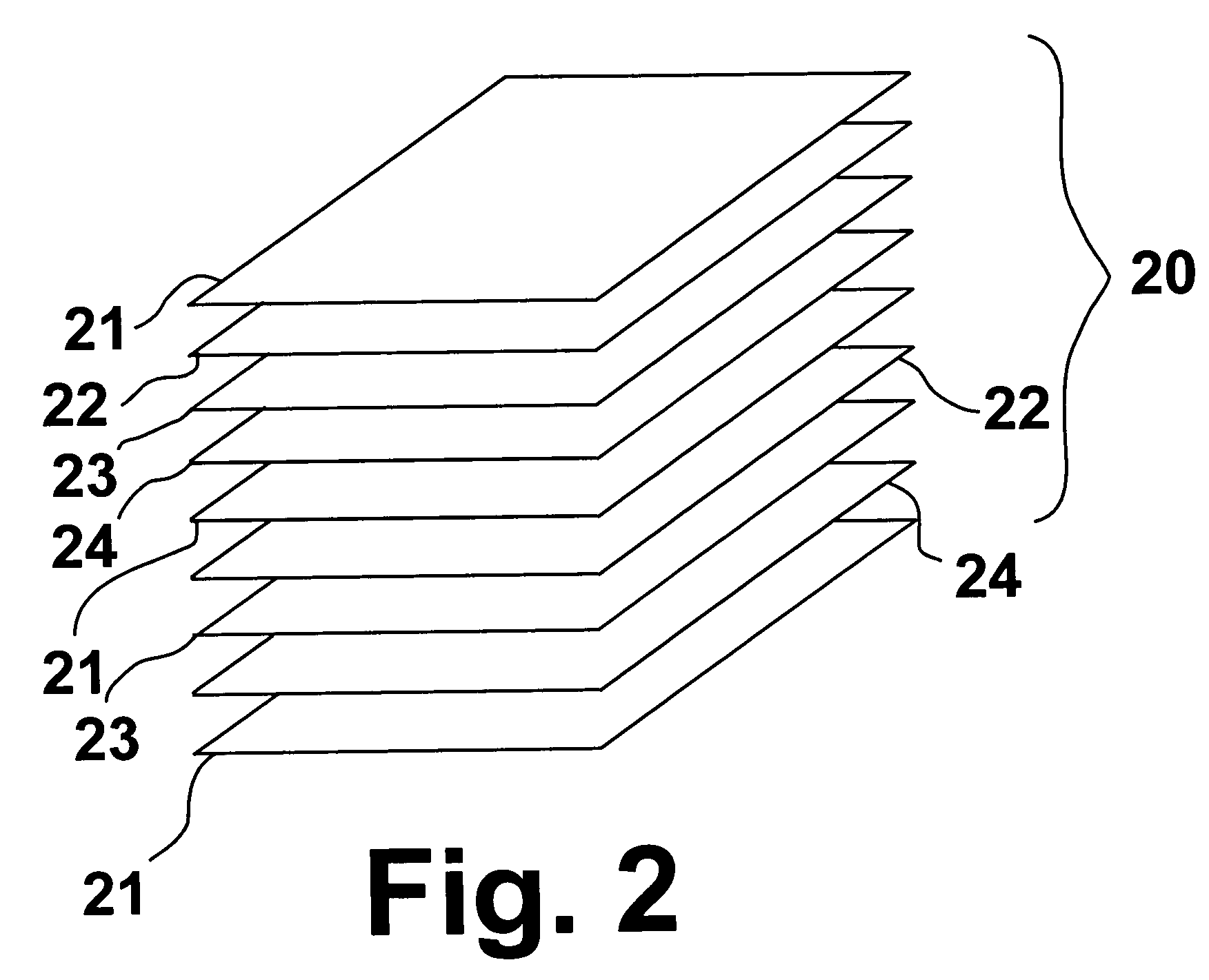
[0040]As shown in FIG. 2, a solid oxide fuel cell stack 20 suitable for use in the system of this invention comprises a plurality of generally planar, rectangular solid oxide fuel cell units, each said solid oxide fuel cell unit comprising an anode electrode 22, a cathode electrode 24 and an electrolyte 23 disposed there between. A bipolar separator plate 21 is disposed between the anode electrode of one solid oxide fuel cell unit and the cathode electrode of an adjacent solid oxide fuel cell unit. The fuel cell units are stacked and provided with endplates, forming half cells at each end and clamped to provide rigid structure to the fuel cell stack. For purposes of this disclosure, it should be noted that all discussions regarding orientation of the components of the system of this invention are relative to the stacking direction of the fuel cell stack as indicated by arrow 15 in FIG. 1. Thus, the top and bottom of the fuel cell stack are defined by the endplates and the sides 19 o...


PUM

PropertyMeasurementUnit
thermal emissivityaaaaaaaaaa
distanceaaaaaaaaaa

Abstract

A generally planar, rectangular solid oxide fuel cell stack having a plurality of fuel cell units, each of the fuel cell units having an anode, a cathode and an electrolyte disposed there between, at least one bipolar separator plate disposed between the anode electrode of one fuel cell unit and the cathode electrode of an adjacent fuel cell unit, an oxidant manifold for delivering oxidant to the cathode electrode, a fuel manifold for delivering fuel to the anode electrode, an anode exhaust gas removal manifold for removing anode exhaust gases from the solid oxide fuel cell stack, and a cathode exhaust gas removal manifold for removing cathode exhaust gases from the solid oxide fuel cell stack. At least one ducted gas flow panel is disposed proximate the fuel cell stack and configured in combination with the fuel cell stack to preheat oxidant gas flowing therethrough and, thus, maintain the fuel cell stack in an operational condition without supplemental heating of the oxidant after entering the at least one ducted gas flow panel.

Description

BACKGROUND OF THE INVENTION[0001]1. Field of the Invention[0002]This invention relates to integrated solid oxide fuel cell systems and thermal management thereof using gas flow panels that absorb thermal radiation from one or more fuel cell stacks. The systems contain at least one gas flow panel that provides oxidant preheating. The systems may also contain additional gas flow panels that provide further oxidant preheating, fuel preheating, fuel pre-reforming, fuel reforming or fuel desulfurization.[0003]2. Description of Related Art[0004]Generally, fuel cell electrical output units are comprised of a stacked multiplicity of individual fuel cell units separated by bi-polar electronically conductive separator plates. Individual fuel cell units are sandwiched together and secured into a single-staged unit to achieve a desired fuel cell power output. Each fuel cell unit generally includes an anode electrode, a cathode electrode, a common electrolyte disposed between the anode electrode...

Claims


Application Information

Patent Timeline
Patent Type & Authority Patents(United States)
IPC IPC(8): H01M8/04H01M8/24
CPCH01M8/04014H01M8/04089H01M8/2425H01M8/02Y02E60/50H01M8/2428H01M8/2432H01M8/2483
Inventor JEWULSKI, JOHN R.KRIST, KEVINSISHTLA, CHAKRAVARTHYPONDO, JOEPETRI, RANDYGOODWIN, DAVE
Owner GAS TECH INST
Features
  • R&D
  • Intellectual Property
  • Life Sciences
  • Materials
  • Tech Scout
  • Unparalleled Data Quality
  • Higher Quality Content
  • 60% Fewer Hallucinations
Learn More