Plasma display panel driving circuit
a driving circuit and plasma display technology, applied in the direction of instruments, static indicating devices, etc., can solve the problems of difficult reduction of cost of energy recovery circuit, large amount of required components, and considerable power consumption of pdp display, so as to reduce the number of components and reduce the voltage stress of some components in the driving circuit.
- Summary
- Abstract
- Description
- Claims
- Application Information
AI Technical Summary
Benefits of technology
Problems solved by technology
Method used
Image

Examples
first embodiment
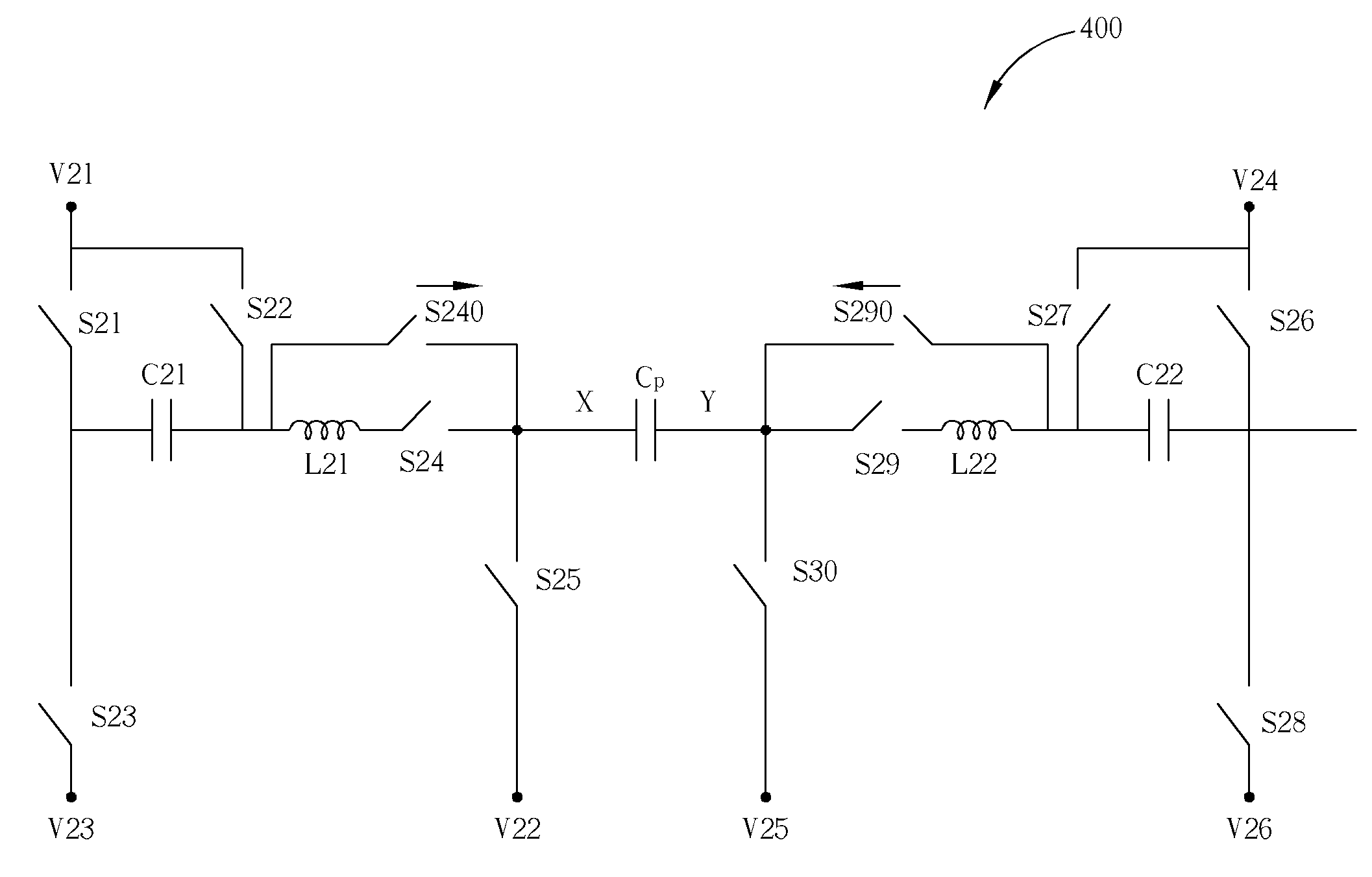
[0041]Please refer to FIG. 4. FIG. 4 shows a circuit diagram of a plasma display panel driving circuit 400 according to the present invention. The driving circuit 400 is shown having an equivalent panel equivalent capacitor Cp of the PDP, and has an X side and a Y side. The driving circuit 400 comprises switches S21 to S30, S240, and S290, capacitors C21 and C22, inductors L21 and L22, and voltage sources V21 to V26. Switches S240 and S290 are unidirectional switches, and the direction of the current is indicated by the arrows in FIG. 4. The current direction of switch S240 is toward the X side of the panel equivalent capacitor Cp, and the current direction of switch S290 is toward the Y side of the panel equivalent capacitor Cp. The voltage potential output by voltage source V21 is greater than that of the voltage sources V22 and V23. Likewise, the voltage potential output by the voltage source V24 is greater than that of the voltage sources V25 and V26. The voltage potentials outp...
second embodiment
[0042]Please refer to FIG. 5. FIG. 5 is shows a circuit diagram of a plasma display panel driving circuit 500 according to the present invention. The driving circuit 500 is a special case of the driving circuit 400 shown in FIG. 4 in which the voltage sources V21 and V24 are the same positive voltage sources, and are labeled as V3 in FIG. 5. In addition, voltage sources V22, V23, V25, and V26 are all ground. All other components of the driving circuit 500 are the same as the driving circuit 400, and switches S211 to S219, S310, S241, and S291, inductors L211 and L212, and capacitors C211 and C212 correspond to switches S21 to S30, S240, and S290, inductors L21 and L22, and capacitors C21 and C22, respectively.
[0043]Please refer to FIG. 6, which illustrates the operation of the driving circuit 500 of the second embodiment for creating a sustain waveform. Steps contained in the flowchart will be explained as follows.
[0044]Step 600: Start.
[0045]Step 602: The switches S212, S213, S215, ...
third embodiment
[0056]Please refer to FIG. 7. FIG. 7 shows a circuit diagram of a plasma display panel driving circuit 700 according to the present invention. The driving circuit 700 comprises switches S31 to S39, a capacitor C31, inductors L31 and L32, and voltage sources V31 to V34. The driving circuit 700 has an equivalent panel equivalent capacitor Cp of the PDP, which has an X side and a Y side. Switches S38 and S39 are unidirectional switches. As indicated by the arrows in FIG. 7, the current direction of switch S38 is toward the X side of panel equivalent capacitor Cp and the current direction of switch S39 is toward the Y side of panel equivalent capacitor Cp. The voltage potential output by voltage source V31 is greater than that of the voltage sources V32, V33, and V34. The voltage potentials output by the voltage sources V32, V33, and V34 can be the same or can be different. Inductor L31 and switch S34 are electrically connected in series, and inductor L32 and switch S36 are also electri...
PUM
 Abstract
Description
Claims
Application Information
 - R&D
- Intellectual Property
- Life Sciences
- Materials
- Tech Scout
- Unparalleled Data Quality
- Higher Quality Content
- 60% Fewer Hallucinations
Browse by: Latest US Patents, China's latest patents, Technical Efficacy Thesaurus, Application Domain, Technology Topic, Popular Technical Reports.
© 2025 PatSnap. All rights reserved.Legal|Privacy policy|Modern Slavery Act Transparency Statement|Sitemap|About US| Contact US: help@patsnap.com