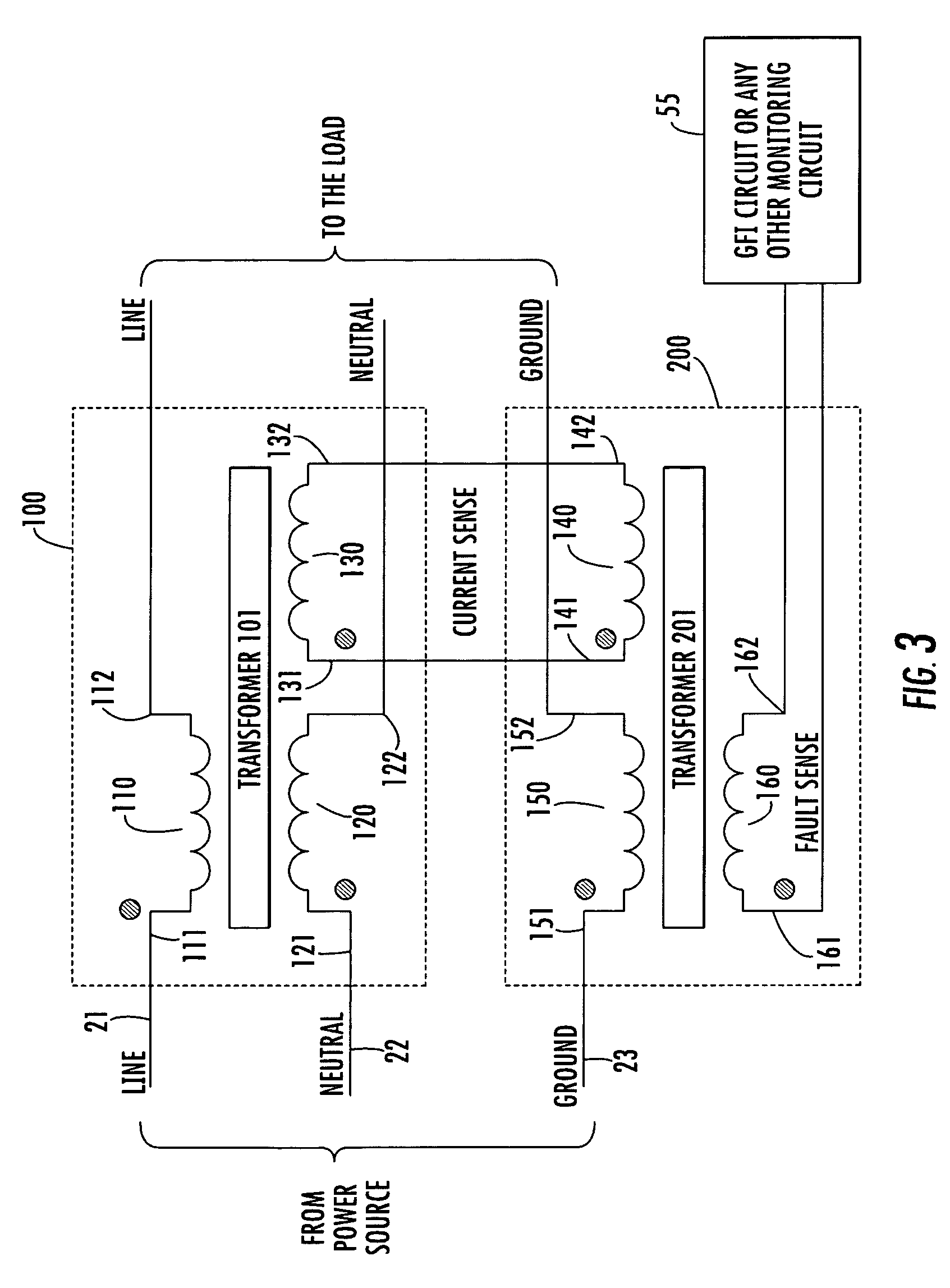
[0005]In accordance with the present invention, this problem is successfully addressed by a new and improved transformer-based ground fault interruption circuit, which employs an auxiliary, toroidally configured transformer interface, trifilar or quadrifilar windings of which are selectively distributed in the line, neutral and earth ground lead paths, in such a manner that only a true ground fault will trigger the opening of a ground fault interrupt switch. Pursuant to a first, dual transformer embodiment of the invention, the ‘hot’ line lead of a power supply cable
plant is coupled through a first winding of a first toroidally wound transformer core to one of the normally closed contacts of a ground fault interrupt switch feeding an electrically driven load (appliance, equipment). The use of a toroidal transformer configuration is preferred, as it confines the magnetic fields produced by its windings to the circular core and isolates the fields from external fields, making it self-shielding. Using trifilar and quadrifilar windings enhances
coupling between the windings and helps cancel external
common mode noise associated with external electrostatic and magnetic fields. Moreover, trifilar and quadrifilar windings enhance
magnetic field cancellation and balance, since each winding wire has the same length and is tightly coupled to the other windings. The number of turns and the winding wire size is based on load current, line frequency and toroid ferrite material.
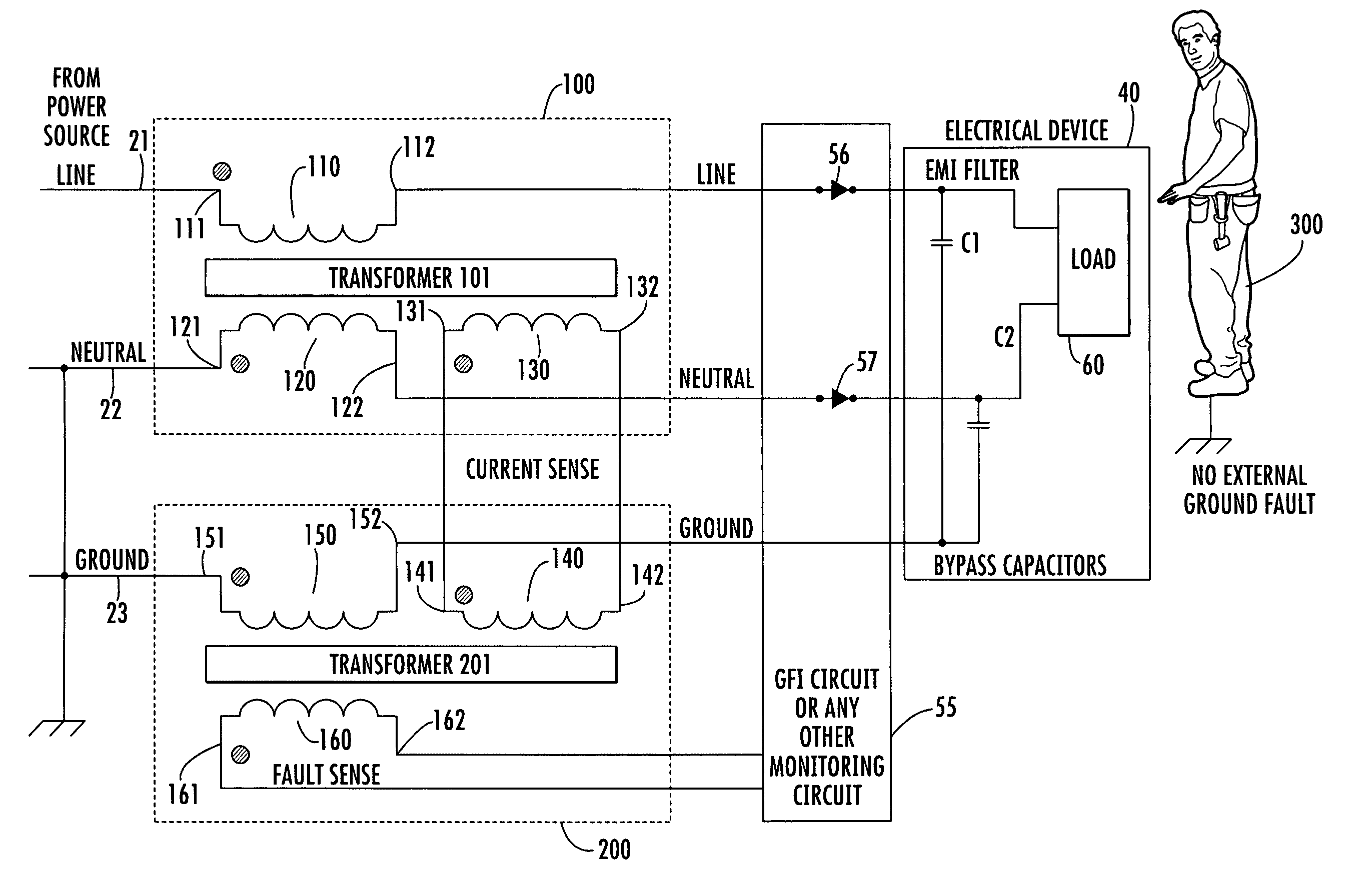
[0011]For the case of a ground fault, associated with a user coming in contact with ground and the load,
line current from the power source cable
plant is coupled through the first transformer winding and then through the line to the normally closed contacts of the GFI switch feeding the load. This flow of
line current through the first winding induces a first
magnetic field component within the toroidal core of the transformer. However, return
neutral current from the load, rather than being coupled through the normally closed contact of the GFI switch, the neutral lead and the second toroidal winding of the transformer is, instead, partially diverted to earth ground by the user, so that the current over the neutral lead is considerably reduced in comparison to that supplied over line. This causes the
magnetic field induced in the transformer core by the current flowing through the second winding to be significantly less than that induced by the first winding, resulting in a substantial non-zero differential magnetic field produced in the core. A further current component is coupled over the earth ground lead to the third winding owing to the presence of the EMI filter capacitors, as in the first embodiment, and induces a
ground current-based magnetic field in the core. However, this magnetic field is much smaller than the substantial, non-zero differential magnetic field induced by the currents supplied to the first and second windings. This means that the magnetic fields induced into the transformer core do not cancel each other, leaving a non-zero differential magnetic field in the transformer core. As a consequence, a
resultant non-zero current is induced in the ground fault sense winding. This current is supplied as a switch activation
signal to the GFI switch from the output leads from the fourth winding, causing its associated contacts open, so as to interrupt the ground fault, and protect the user, as intended.

