Method and device for controlling an internal combustion engine

a technology of internal combustion engine and control device, which is applied in the direction of electric control, ignition automatic control, instruments, etc., to achieve the effect of reliably preventing knocking

Active Publication Date: 2008-05-27
VITESCO TECH GERMANY GMBH
View PDF14 Cites 16 Cited by
  • Summary
  • Abstract
  • Description
  • Claims
  • Application Information

AI Technical Summary

Benefits of technology

[0012]Torque equalization is thus possible in a simple manner through a simple adaptation of the respective individual ignition angle for the group as a function of the decisive loss torque for the respective group and in this way a very limited irregularity of running of the internal combustion engine can be ensured.
[0014]In an advantageous embodiment of the invention, the individual ignition angle is determined for each group as a function of a difference between the decisive loss torque for the respective group and the decisive loss torque for another group. In this way, very good equalization of the torques of the cylinders can be effected in a simple manner if, depending on the desire of the driver, the indicated torque is determined with no distinction being made between the different loss torques for the respective groups but a mean loss torque effective per working cycle of the internal combustion engine being taken as the basis.
[0015]According to a further advantageous embodiment of the invention, the individual ignition angle is limited to a minimum and / or to a maximum ignition angle. In this way, if the minimum and maximum ignition angle are chosen suitably, the occurrence of knocking or ignition failures or inadmissibly high exhaust gas temperatures can be prevented in a simple manner.
[0016]According to a further advantageous embodiment of the invention, when an individual ignition angle which is associated with a group reaches the minimum ignition angle, another individual ignition angle which is associated with another group is determined as a function of the minimum ignition angle. Ignition failures and inadmissibly high exhaust gas temperatures can in this way reliably be prevented and also, as far as possible, the desired torque set for low running irregularity.
[0017]According to a further advantageous embodiment of the invention, when a cylinder-specific ignition angle which is associated with a group of cylinders reaches the maximum ignition angle, another individual ignition angle which is associated with another group of cylinders is determined as a function of the maximum ignition angle. Knocking can reliably be prevented in this way and also, as far as possible, the desired torque set for low running irregularity.

Problems solved by technology

This is a major challenge particularly at working points at which some of the gas intake valves are being operated with a high valve lift and others with a low valve lift.

Method used


Image

  • Method and device for controlling an internal combustion engine
  • Method and device for controlling an internal combustion engine
  • Method and device for controlling an internal combustion engine

Examples


Embodiment Construction

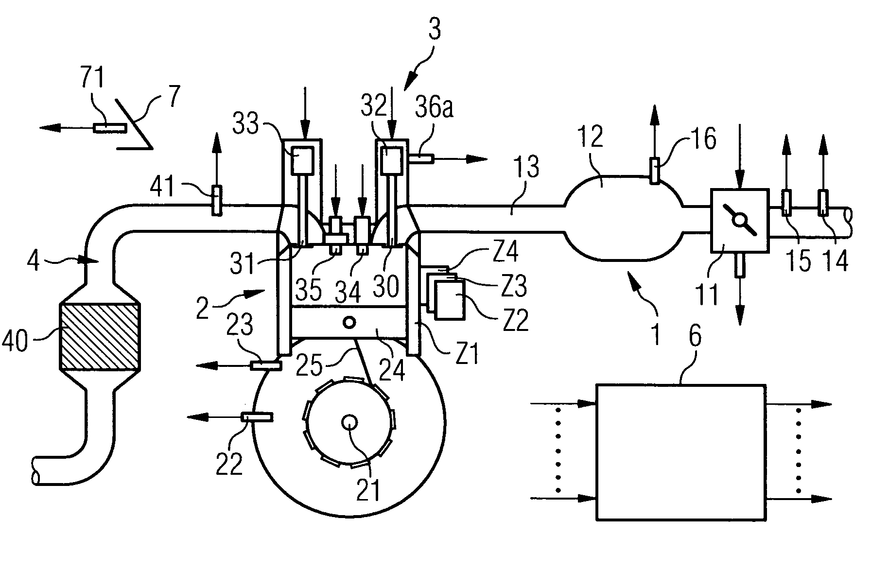
[0024]An internal combustion engine (FIG. 1) comprises an intake manifold 1, an engine block 2, a cylinder head 3 and an exhaust manifold 4. The intake manifold preferably comprises a throttle valve 11, and also an accumulator 12 and a suction pipe 13 which is guided to a cylinder Z1 via an inlet channel into the engine block 2. The engine block 2 also comprises a crankshaft 21 which is connected via a connecting rod 25 to the piston 24 of the cylinder Z1.

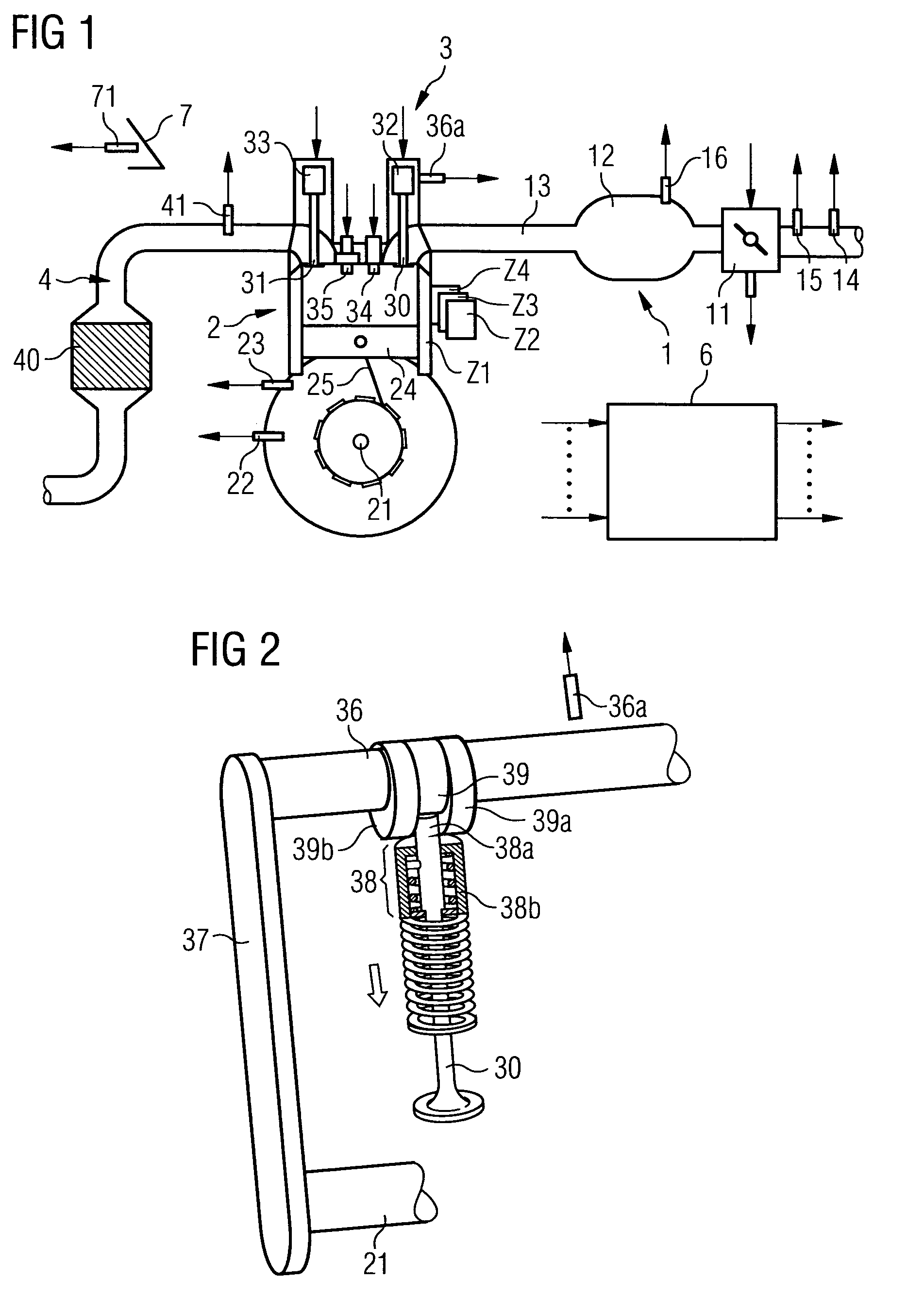
[0025]The cylinder head 3 comprises a valve drive having a gas intake valve 30, a gas outlet valve 31 and valve actuators 32, 33. The gas intake valve 30 and the gas outlet valve 31 are actuated by means of a camshaft 36 (FIG. 2) on which cams 39, 39a and 39b are fashioned, which cams act upon the gas intake valve 30. Cams that are not shown are also provided, optionally on a further camshaft, which cams act upon the gas outlet valve 31.

[0026]A total of three cams 39, 39a, 39b (FIG. 2) are associated with the gas intake valve. The ...


PUM


Abstract

An internal combustion engine has a plurality of cylinders having combustion chambers and each being associated with a spark plug designed for igniting a mixture of air and fuel in the combustion chamber, and at least two adjusting devices for adjusting the air supply to the combustion chambers of the different cylinders. To control the internal combustion engine, an individual ignition angle is detected for each group of cylinders to which the same air mass per working cycle is respectively supplied and during the respective working cycles of which the same loss torque is decisive. The decisive loss torque is the one associated with the cylinder that is in its intake cycle during the respective working cycle of the respective cylinder of the respective group. The individual ignition angle for each group is detected as a function of the decisive loss torque for the respective group.

Description

CROSS REFERENCE TO RELATED APPLICATIONS[0001]This application is the US National Stage of International Application No. PCT / EP2005 / 050688, filed Feb. 16, 2005 and claims the benefits of German Patent application No. 10 2004 022 593.1 filed May 7, 2004. All of the applications are incorporated by reference herein in their entirety.FIELD OF INVENTION[0002]The invention relates to a method and a device for controlling an internal combustion engine.BACKGROUND OF THE INVENTION[0003]Increasingly high demands are being placed on internal combustion engines with regard to their performance and efficiency. At the same time, because of strict legal regulations, emissions must also be low. Such demands can readily be met if the internal combustion engine is fitted with gas-changing valves and corresponding actuators for said valves, in which the valve lift characteristic varies depending on the working point of the internal combustion engine. By this means, throttle losses upon intake of air c...

Claims


Application Information

Patent Timeline
Patent Type & Authority Patents(United States)
IPC IPC(8): F02P5/15F02D41/14F02D41/00F02D41/34
CPCF02P5/151F02D41/008F02D2041/001F02D2200/1006F02D2250/18Y02T10/46Y02T10/40F02P5/15
Inventor JEHLE, MARTINSCHNEIDER, DIRK
Owner VITESCO TECH GERMANY GMBH
Why Eureka
Try Eureka