
Fluid regulating microvalve assembly for fluid consuming cells

a micro-valve and fluid-consuming technology, applied in the direction of cell components, cell component details, electrochemical generators, etc., can solve the problems of limited maximum discharge rate, and reduced material use in oxygen reduction electrodes. low cost, inexpensive and simple to produce

Inactive Publication Date: 2008-05-27
SCHUMM BROOKE JR +3
View PDF37 Cites 2 Cited by
  • Summary
  • Abstract
  • Description
  • Claims
  • Application Information

AI Technical Summary

Benefits of technology

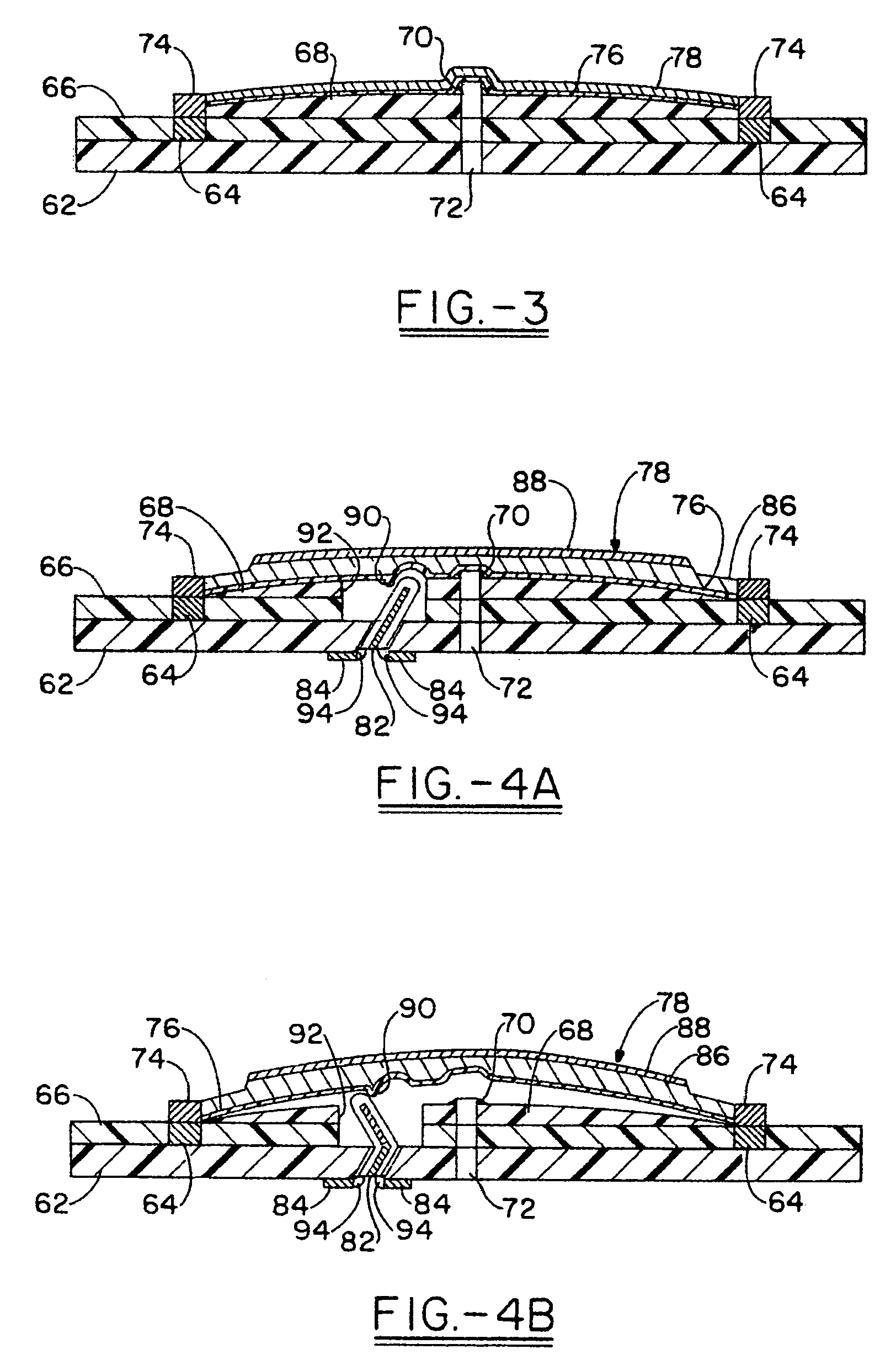
"The present invention provides a low-cost, reliable fluid regulating microvalve assembly for electrochemical cells. The microvalve assembly is small in size and takes up little volume in the cell, maximizing the volume for energy producing components. The microvalve assembly allows high rate discharge of the cell with relatively low or no capacity loss during periods of low rate or no discharge. The invention also provides a multi-layer microvalve assembly that can have a complex configuration and be efficiently and economically produced at high speeds. The microvalve assembly is operatively joined to a microactuator that is thermally actuated and capable of moving between a first position where fluid cannot pass through the microvalve body aperture and a second position where fluid can pass through the microvalve body aperture. The microactuator is formed by one or more layers of a polymer, elastomer or rubber material that are operatively joined to the microvalve body. The microvalve body has an aperture that extends through the body from a first surface to a second surface. The microactuator is connected to the microvalve body and capable of moving between a first position where fluid cannot pass through the microvalve body aperture and a second position where fluid can pass through the microvalve body aperture."

Problems solved by technology

However, some materials used in oxygen reduction electrodes are not true catalysts because they can be at least partially reduced, particularly during periods of relatively high rate discharge.
A disadvantage of these cells is that the maximum discharge rates they are capable of can be limited by the rate at which oxygen can enter the oxygen reduction electrode.
However, changing the diffusion rate of one of these gases generally affects the others as well.
Even when efforts have been made to balance the need for a high rate of oxygen diffusion and low rates of CO2 and water diffusion, there has been only limited success.
To provide an increase in air flow into the cell only during periods of high rate discharge, fans have been used to force air into cells (e.g., U.S. Pat. No. 6,500,575), but fans and controls for them can add cost and complexity to manufacturing, and fans, even micro fans, can take up valuable volume within individual cells, multiple cell battery packs and devices.
However, the pressure differential may be small and can be affected by the atmospheric conditions outside the battery.

Method used


Image

  • Fluid regulating microvalve assembly for fluid consuming cells
  • Fluid regulating microvalve assembly for fluid consuming cells
  • Fluid regulating microvalve assembly for fluid consuming cells

Examples


Embodiment Construction

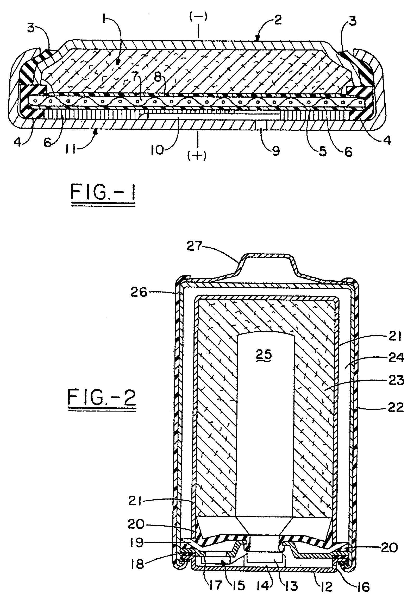
[0034]In one embodiment of the invention, a fluid regulating microvalve assembly is operatively connected to a cell that uses a fluid, such as oxygen or other gas or gases, from an exterior of the cell, such as the surrounding atmosphere, as an active material for an electrode present in the interior of the cell. The fluid regulating microvalve assembly controls the flow rate of fluid between the exterior and interior of the cell and ultimately the flow rate to a fluid consuming electrode, such as an oxygen reduction electrode. The cell can be a fuel cell such as a methanol or hydrogen fueled oxygen cell, an air-depolarized cell, or an air-assisted cell as known in the art. Other possible cell types include, but are not limited to, chlorine or bromine depolarized cells. Also, the microvalve assemblies of the present invention can be used in “reserve” cells where the fluid admitted into a predetermined area of the cell by the microvalve assembly is stored in a separate reservoir unti...


PUM

PropertyMeasurementUnit
thicknessaaaaaaaaaa
thicknessaaaaaaaaaa
widthaaaaaaaaaa

Abstract

A fluid regulating microvalve assembly for use to control fluid flow to a fluid consuming electrode, such as an oxygen reduction electrode, in an electrochemical cell. The microvalve assembly includes a stationary valve body having an aperture and a microactuator movable from a first position where the microvalve body aperture is closed to fluid flow to at least a second position where fluid is able to pass through the microvalve body aperture. The fluid regulating microvalve assembly can utilize cell potential or a separate source to open and close the microvalve. The fluid regulating microvalve assembly can be located outside the cell housing or inside the cell housing, for example between one or more fluid inlet apertures and the fluid consuming electrode. The invention includes a method of making a multilayer microvalve assembly, particularly one for use in a fluid depolarized battery, using a printing process to deposit at least one of the layers.

Description

CROSS-REFERENCE TO RELATED APPLICATIONS[0001]This application claims the benefit of U.S. Provisional Application No. 60 / 522,704, filed Oct. 29, 2004.FIELD OF THE INVENTION[0002]The present invention relates to fluid regulating microvalve assemblies adapted to control the rate of flow of one or more fluids, particularly a gas, between an interior and an exterior of a cell housing of a cell, such as a fuel cell or battery that is preferably air-depolarized or air-assisted, as well as fuel cells and batteries containing the fluid regulating microvalve assemblies. Methods for preparing fluid regulating microvalve assemblies and cells containing the microvalve assemblies are disclosed.BACKGROUND OF THE INVENTION[0003]Electrochemical battery cells that use a fluid, such as oxygen or other gas(es), from outside the cell as an active material to produce electrical energy, such as air-depolarized, air-assisted and fuel cell battery cells, can be used to power a variety of electronic devices....

Claims


Application Information

Patent Timeline
Patent Type & Authority Patents(United States)
IPC IPC(8): H01M4/00H01M2/12H01M2/36H01M50/609H01M50/627
CPCH01M2/1229H01M2/361H01M12/06H01M8/04201Y02E60/50Y02E60/10H01M50/325H01M50/609H01M50/627
Inventor SCHUMM, JR., BROOKE
Owner SCHUMM BROOKE JR
Learn More