
User interface for reporting event-based production information in product manufacturing

a product manufacturing and user interface technology, applied in adaptive control, process and machine control, instruments, etc., can solve the problems of insufficient manpower, inability to obtain raw materials, and previous efforts to adequately document and analyze the many factors

Active Publication Date: 2008-05-27
CALLAHAN CELLULAR L L C
View PDF88 Cites 143 Cited by
  • Summary
  • Abstract
  • Description
  • Claims
  • Application Information

AI Technical Summary

Benefits of technology

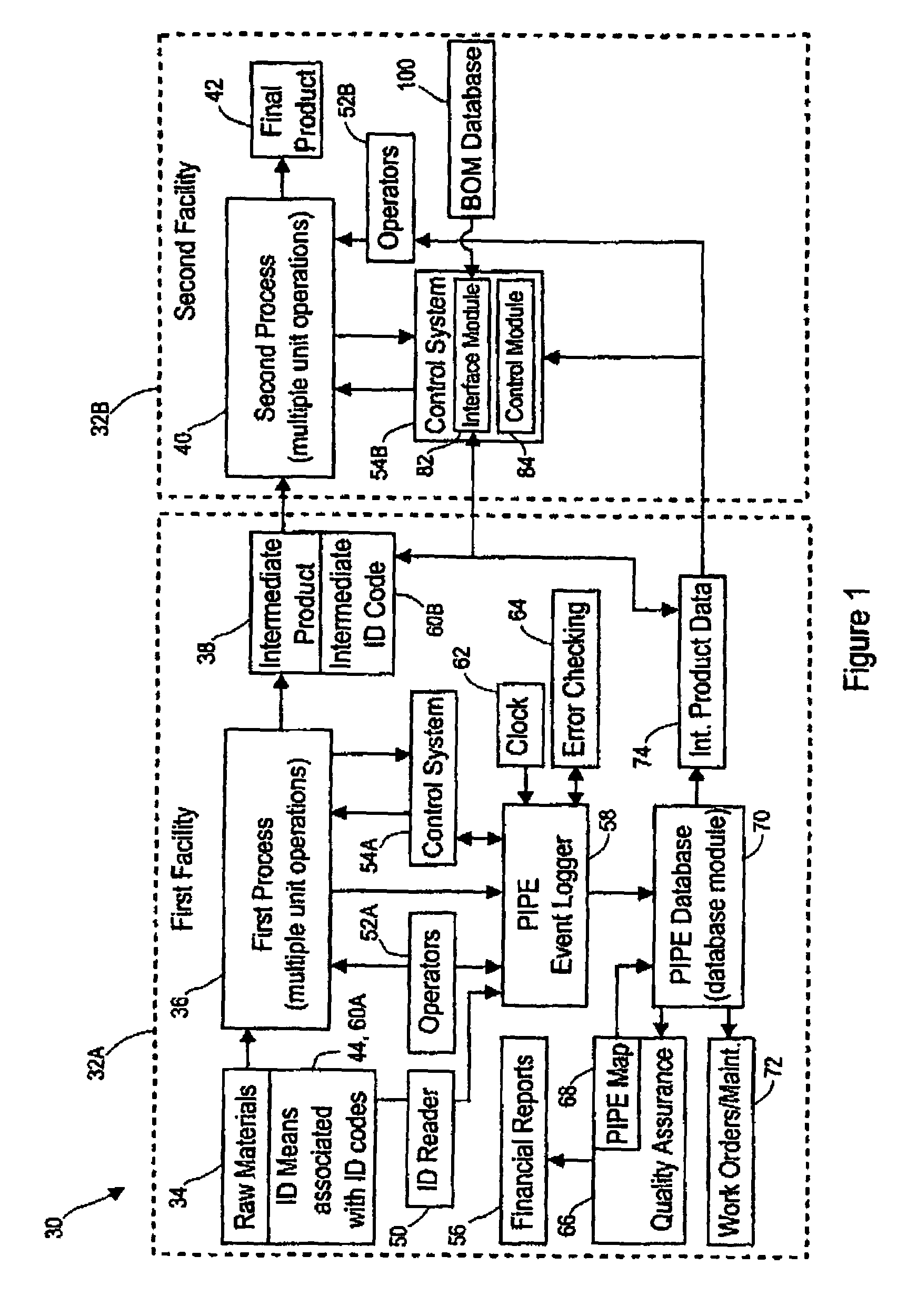
[0008]The invention is operable in an intelligent manufacturing system including a process for converting raw materials to a product, a process control system including one or more sensors capable of generating an alarm in response to an event that results in one of waste, machine delay, or decrease product quality, a data logger associated wit

Problems solved by technology

In manufacturing, the realized capacity of a machine or production facility may be substantially less than the theoretically maximum capacity for any number of reasons, including machine stoppage or delay caused by quality problems, machine failure, inadequate manpower, unavailable raw materials, and the like.
Previous efforts have failed to adequately document and analyze the many factors that may be associated with machine delay or other productivity problems.
Further, a manufacturing information system does not yet appear to have been developed which can directly provide accounting data for financial reports based on data obtained directly from a manufacturing site pertaining to process events and associated productivity parameters.
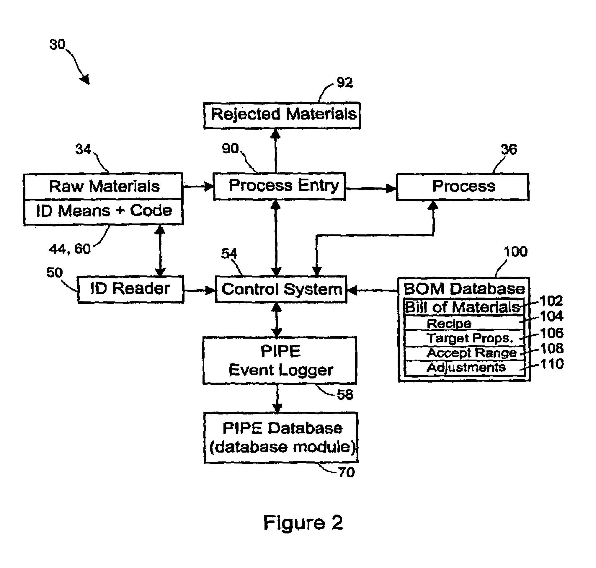
Further, in the production of goods from raw materials and intermediate components, it is an ongoing challenge to ensure that proper raw materials are used, and to track the effect of the raw materials on the productivity of a machine.
For example, using present systems, it is often possible for an incorrect raw material to be loaded into a process, and that process may continue to operate for hours, yielding product that does not comply with specifications, sometimes resulting in enormous waste.

Method used


Image

  • User interface for reporting event-based production information in product manufacturing
  • User interface for reporting event-based production information in product manufacturing
  • User interface for reporting event-based production information in product manufacturing

Examples


example 1

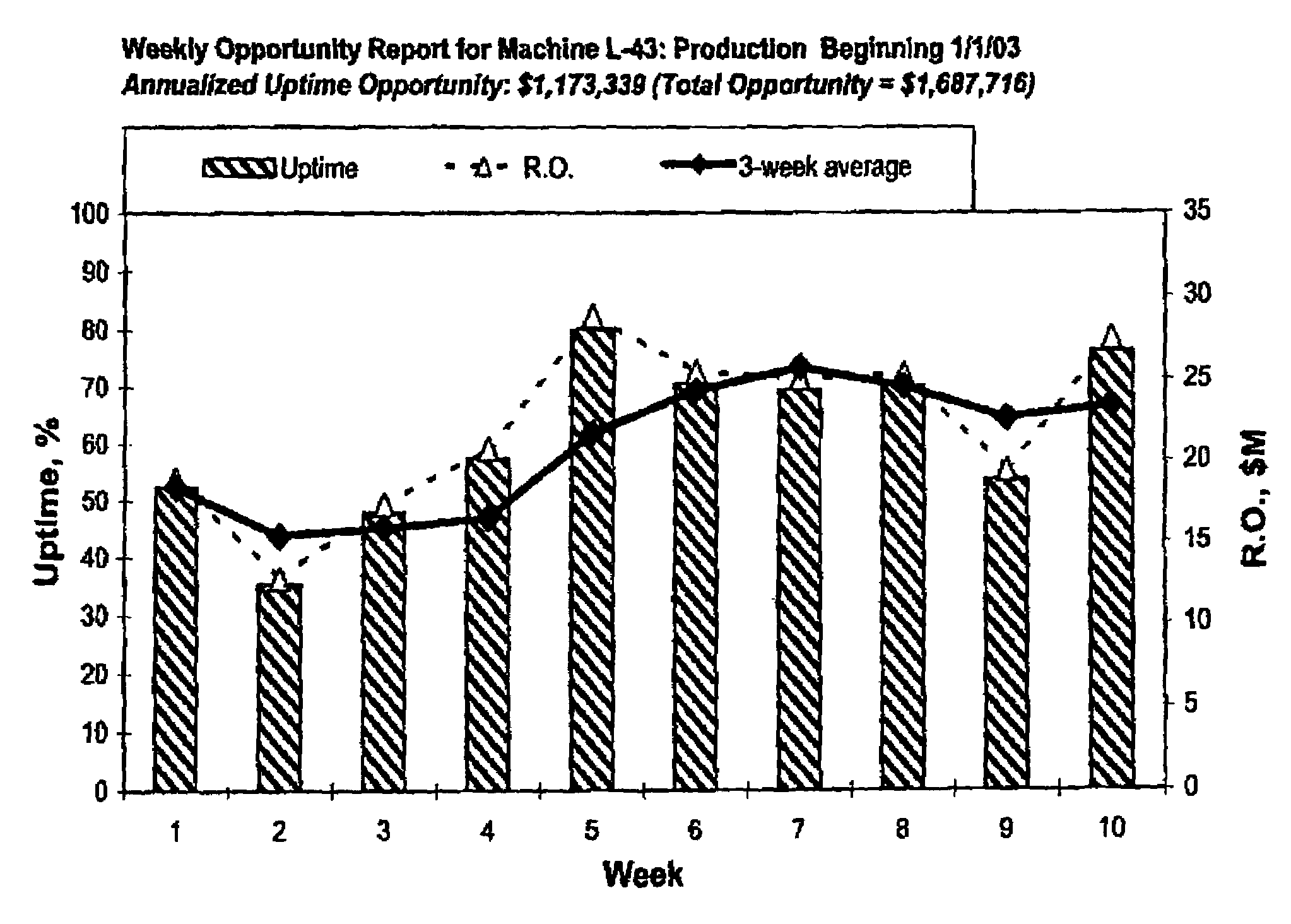
[0263]A raw material change was implemented across a number of production facilities, resulting in direct cost savings over the previous material. There was a strong perception among employees at the production level that this new material caused a number of processing problems and had a deleterious effect on machine uptime. Increased process interruptions and machine downtime may potentially negate the savings achieved with the raw material change.

[0264]Anecdotal evidence from production facilities caused concern that overall cost savings might not be what was expected because of the increased processing difficulties. Although it seemed clear that some facilities were experiencing difficulties with the new material, a total cost savings analysis was difficult because different machines changed to the material at different times. Further, the facilities tended to use different criteria for determining the impact of the new material, and once some machines experienced problems, sensi...

example 2

[0269]In the production of an article including a web, the web had been slitted to a narrow width suitable for the article. The narrow roll of the slitted web used as a raw material was produced in another process by slitting a wider roll of the web material. Each slitted roll of the web material was tracked with bar code information that identified the roll, its date and place of manufacturer, and its position on the slitter. The slitter had a plurality of slitter blades and formed a plurality of narrow slitted sections of the web numbered from 1 to N, where N is the number of slit sections and N−1 is the number of slitter blades used. The outer positions of the web were sections 1 and N, while the central position of the web was position N / 2 (for even N). The rolls of raw material were used on a machine for producing an article. The machine was equipped with a PIPE system to track process events such as waste and delay at various locations in the machine. Over a period of time, pr...

example 3

[0272]This example deals with analysis of actual PIPE data obtained with a proprietary PIPE-based manufacturing system in which manufacturing events from a consumer products machine were recorded over time. The machine processed a variety of raw materials, including webs of material provided in roll form. To maintain a continuous web being fed into the machine, web splices were routinely performed, particularly between the tail end of one roll and the leading edge of the next roll.

[0273]During the review of PIPE summary data of machine stops and delay on the consumer products machine, a particular machine section was identified as contributing an excessively large percent of the total number of daily machine stops. A number of possible reasons for the increased section stops were hypothesized, some of which were connected to various other events that occurred on the machine. In particular, various raw material splice events were suspected as possible causes for the increased stops i...


PUM


Abstract

User interface for reporting event-based production information in product manufacturing. Some of the disclosed embodiments include a system, method, computer-readable medium, and display device for processing data stored in a database. The data includes automatically collected event-based production information records in a manufacturing system wherein each record represents an event and includes a timestamp, an event code, and a measure of cost or production loss associated with the event. The embodiments are operable in an intelligent manufacturing system including a process for converting raw materials to a product, a process control system including one or more sensors capable of generating an alarm in response to an event that results in one of waste, machine delay, or decrease product quality, a data logger associated with the process control system for obtaining event parameters associated with the event, a database on a server for recording event parameters obtained by the data logger, and a reporting system cooperatively associated with the database for reporting productivity parameters regarding the process derived at least in part from the event parameters.

Description

CROSS-REFERENCE TO RELATED APPLICATIONS[0001]This application claims the benefit of U.S. Provisional Application No. 60 / 344,747, filed Dec. 28, 2001, herein incorporated by reference.TECHNICAL FIELD[0002]The present invention relates to the field of product manufacturing. In particular, this invention relates to a user interface for reporting event-based production information in product manufacturing.BACKGROUND[0003]In manufacturing, the realized capacity of a machine or production facility may be substantially less than the theoretically maximum capacity for any number of reasons, including machine stoppage or delay caused by quality problems, machine failure, inadequate manpower, unavailable raw materials, and the like. Many attempts have been made to improve statistical process control of machines and plants to improve quality, and other efforts have been made to optimize machine maintenance, raw materials purchasing, inventory management and so forth to generally increase produ...

Claims


Application Information

Patent Timeline
IPC IPC(8): G06F3/00G06F17/00G06F9/00B23Q35/12G05B13/02G06N5/04G06Q10/06G06Q10/10
CPCB23Q35/12G05B13/0285G06N5/048G06Q10/06G06Q10/10
Inventor POKORNY, MICHAEL ROYBARBER, DOUGLAS GORDON BARRONHOO, WINNIE SHI MEI SHUNLINDSAY, JEFFREY DEANMARKHAM, CHARLES EARLMATHEUS, JON RAYMORK, JAMIE SCOTTNYGAARD, KURT SIGURDREADE, WALTER CASWELLSTAMBUK, JOSE ANDRES
Owner CALLAHAN CELLULAR L L C
Learn More