Rotary compressor having a stepped cover of a discharge muffler chamber

a rotary compressor and discharge muffler technology, which is applied in the direction of machines/engines, liquid fuel engines, applications, etc., can solve the problems of sudden rise in production costs of rotary compressors, difficult to reduce dimensional tolerances, and complicated working of lower support members, so as to reduce fluctuations of dimensional tolerances and work easy

Inactive Publication Date: 2008-06-03
SANYO ELECTRIC CO LTD
View PDF10 Cites 7 Cited by
  • Summary
  • Abstract
  • Description
  • Claims
  • Application Information

AI Technical Summary

Benefits of technology

[0007]The present invention has been developed to solve such problems of the conventional technology, and an object is to improve sealability of an O-ring and a performance of a rotary compressor.
[0011]According to the rotary compressor of the first aspect of the present invention, since the stepped portion to absorb the thickness of the gasket is disposed on the surface of the cover on the side of the support member, the stepped portion can be easily worked.
[0012]Consequently, fluctuations of dimensional tolerances can be reduced, and the dimensional tolerances can be reduced. Therefore, while production costs are reduced, sealability of the O-ring can be improved.
[0013]Especially, when the surface of the cover which abuts on the bearing portion is protruded on the side of the support member as in the second aspect of the present invention, the sealability of the O-ring can be secured without decreasing a volume of the discharge muffler chamber.
[0014]Moreover, in a high inner pressure type rotary compressor in which the refrigerant compressed by the first rotary compression element is compressed by the second rotary compression element and discharged into the sealed container as in the third aspect of the present invention, the present invention is applied to the first rotary compression element having a large pressure difference from the inside of the sealed container. In consequence, a volume efficiency of the first rotary compression element can be improved.

Problems solved by technology

That is, this problem has been handled by protruding an end of the bearing portion as much as the thickness of the gasket on the side of the cover.
However, working of the lower support member becomes complicated, and it is difficult to reduce a dimensional tolerance.
This causes a problem that production costs of the rotary compressor suddenly rise, and sealability by the O-ring deteriorates.

Method used


Image

  • Rotary compressor having a stepped cover of a discharge muffler chamber
  • Rotary compressor having a stepped cover of a discharge muffler chamber
  • Rotary compressor having a stepped cover of a discharge muffler chamber

Examples


Embodiment Construction

[0020]There will be described hereinafter an embodiment of a multistage compression type rotary compressor of the present invention in detail with reference to the drawings.

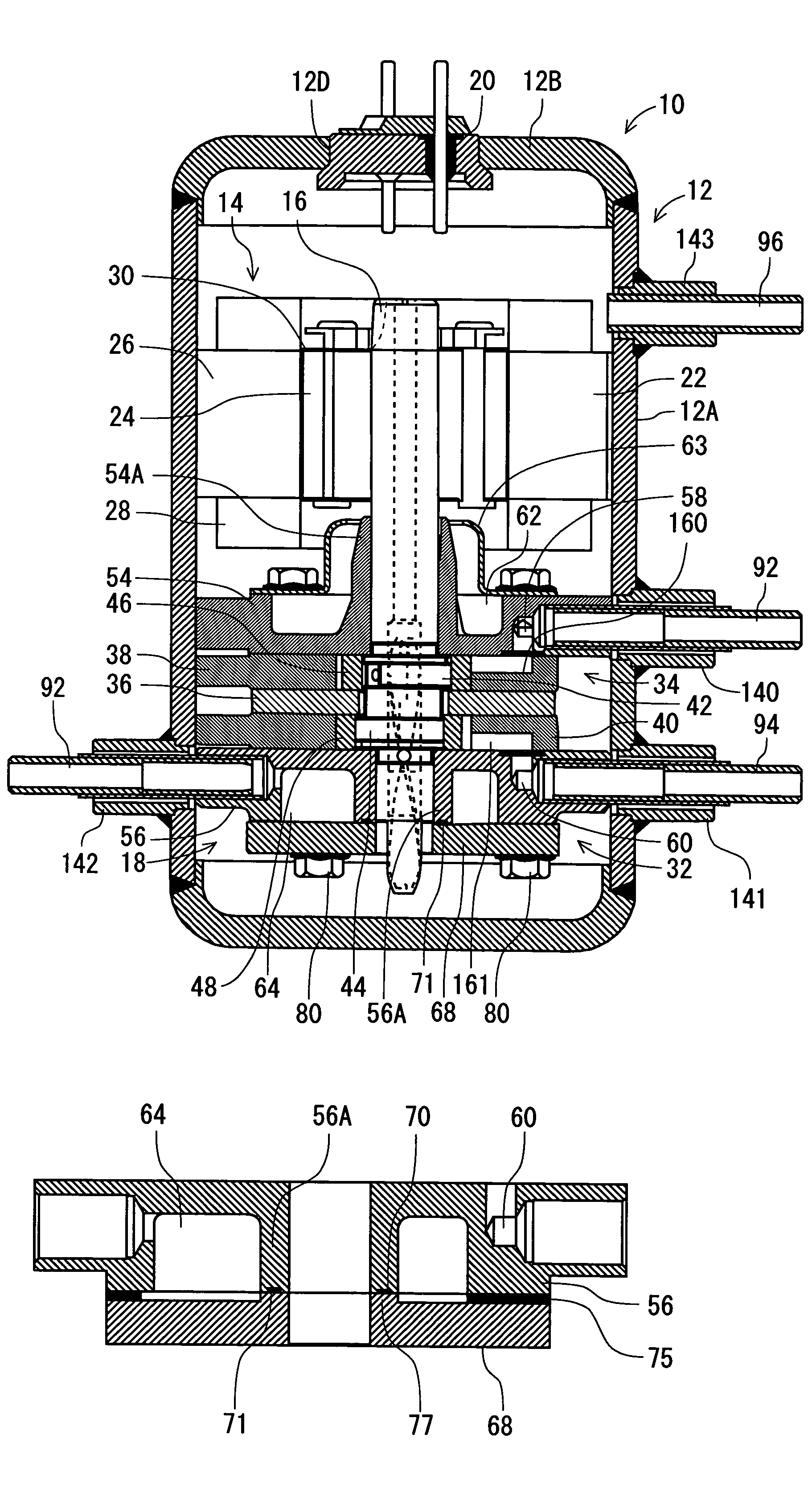
[0021]In FIG. 1, a rotary compressor 10 of the present embodiment is a high inner pressure type rotary compressor in which a rotary compression element is constituted of first and second rotary compression elements 32, 34. A refrigerant compressed by the first rotary compression element 32 is compressed by the second rotary compression element 34 and discharged into a sealed container 12. In the vertical cylindrical sealed container 12 constituted of a steel plate, there are disposed an electromotive element 14 as a driving element disposed in an upper part of an inner space of the sealed container 12, and a rotary compression mechanism section 18 driven by a rotation shaft of the electromotive element 14. It is to be noted that in the present embodiment, carbon dioxide is used as the refrigerant in the rotary co...


PUM


Abstract

A rotary compressor including upper and lower cylinders constituting first and second rotary compression elements; a lower support member which closes an opening of the lower cylinder and which has a bearing as a bearing portion of a rotation shaft; a discharge muffler chamber formed by depressing an outer surface of the bearing of the lower support member on the side opposite to the lower cylinder to close the depressed portion with a lower cover; an O-ring groove formed in the surface of the bearing which abuts on the lower cover; an O-ring stored in the O-ring groove; and a gasket disposed between the lower support member. The lower cover in an outer peripheral portion of the lower support member, and the surface of the lower cover on the side of the lower support member, is provided with a stepped portion to absorb a thickness of the gasket.

Description

BACKGROUND OF THE INVENTION[0001]The present invention relates to a rotary compressor including a driving element and a rotary compression element driven by a rotation shaft of this driving element, the elements being disposed in a sealed container.[0002]Heretofore, this type of rotary compressor, for example, a multistage compression type rotary compressor including first and second rotary compression elements is constituted of a driving element and first and second rotary compression elements driven by a rotation shaft of this driving element, the elements being disposed in a sealed container.[0003]As to the first and second rotary compression elements, the second rotary compression element is disposed on an upper side, and the first rotary compression element is disposed on a lower side via an intermediate partition plate. That is, the first and second rotary compression elements are constituted of: upper and lower cylinders disposed on and under the intermediate partition plate;...

Claims


Application Information

Patent Timeline
Patent Type & Authority Patents(United States)
IPC IPC(8): F03C2/00F03C4/00F04C2/00
CPCF01C21/10F04C23/008F04C27/008F04C18/3564F04C23/001F04C29/06A47J36/2488A47J37/0694A47J37/0786
Inventor SATO, KAZUYA
Owner SANYO ELECTRIC CO LTD
Why Eureka
Try Eureka