Device and working method for automatically changing the work rolls, the back-up rolls and the intermediate rolls of a single-stand or multiple-stand strip mill

a technology of work rolls and working methods, which is applied in the direction of manufacturing tools, ammunition loading, transportation and packaging, etc., can solve the problems of long unfavorable work, and course a stoppage of production, so as to improve the cost-effectiveness, shorten the downtime of the rolling mill, and increase the output

Inactive Publication Date: 2008-06-03
SMS DEMAG AG
View PDF9 Cites 3 Cited by
  • Summary
  • Abstract
  • Description
  • Claims
  • Application Information

AI Technical Summary

Benefits of technology

[0021]With the invention, the downtimes of the rolling mill are shortened considerably. The greater availability of the rolling mill that is consequently achieved increases the output and consequently improves the cost-effectiveness. The automatic feeding of the removal crossbar is additionally much safer for the operating personnel in comparison with the conventional working practice.

Problems solved by technology

With the rolling stand, and as a result the entire rolling mill, at a standstill, there is of course a stoppage of production.
This is particularly unfavorable if, upstream or downstream of the rolling mill, there are other plants, for example a pickling plant, which could actually continue running.
A large number of manual activities during the changing of the backup rolls and crane work require a long downtime of the rolling mill.
In addition, the crane work is more dangerous than the automatic changing of the work rolls and / or intermediate rolls.

Method used


Image

  • Device and working method for automatically changing the work rolls, the back-up rolls and the intermediate rolls of a single-stand or multiple-stand strip mill
  • Device and working method for automatically changing the work rolls, the back-up rolls and the intermediate rolls of a single-stand or multiple-stand strip mill
  • Device and working method for automatically changing the work rolls, the back-up rolls and the intermediate rolls of a single-stand or multiple-stand strip mill

Examples


Embodiment Construction

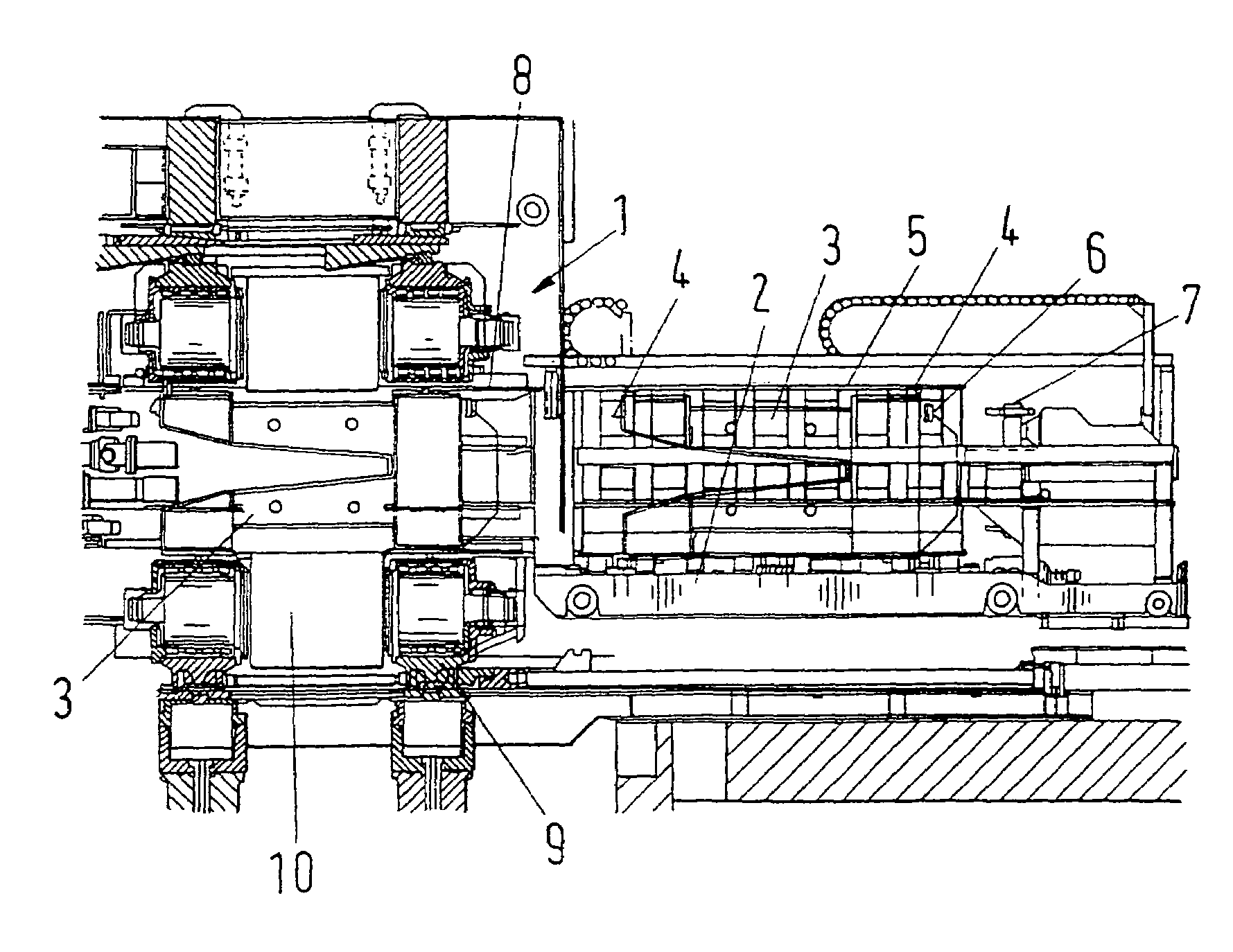
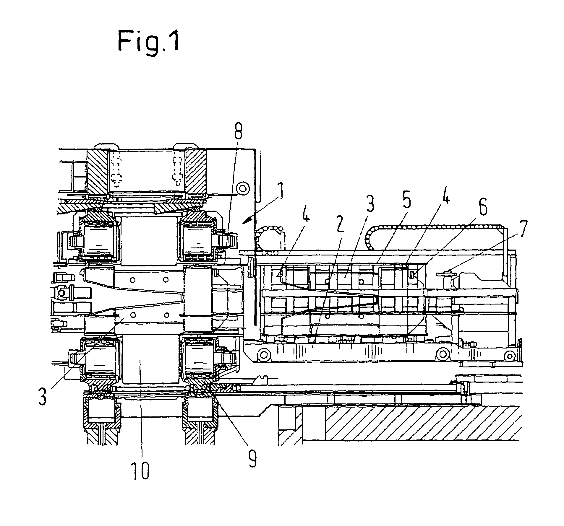
[0026]Represented in a side view in FIG. 1 is a section taken centrally through a known six-roll strip rolling stand 1, in the case of which the set of rolls comprising work rolls and intermediate rolls has already been removed. The set of rolls was pulled out from the strip rolling stand 1 in a known way with the aid of the roll changing carriage 2 and displaced transversely, i.e. perpendicularly in relation to the plane of the drawing, on the roll changing carriage 2.

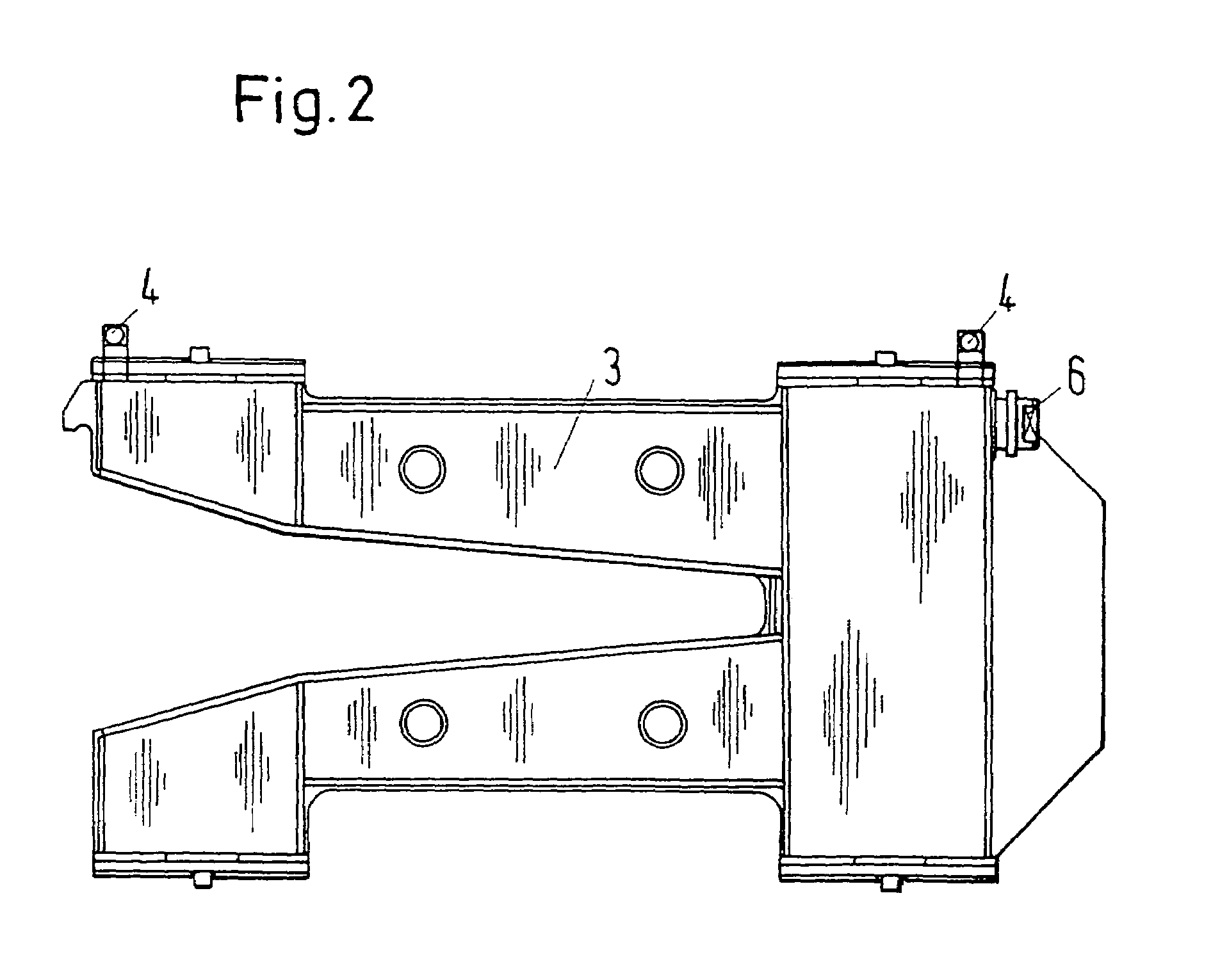
[0027]For the changing of the backup rolls, according to the invention the removal crossbar 3 is used. As FIG. 1 shows, this removal crossbar 3 is positioned on the roll changing carriage 2 laterally next to the set of rolls comprising work rolls and intermediate rolls, and was moved into a position centrally in relation to the strip rolling stand 1 by transverse displacement of the roll changing carriage 2. The set of rolls comprising work rolls and intermediate rolls cannot be seen in FIG. 1; it is concealed by the ...


PUM

PropertyMeasurementUnit
movementaaaaaaaaaa
heightaaaaaaaaaa
timeaaaaaaaaaa

Abstract

A roll changing carriage can be displaced transversely with respect to the strip rolling stand and a removal crossbar is provided for the removal of the set of backup rolls. In order to shorten the roll changing times and to automate the changing of the rolls, the removal crossbar can be positioned on the roll changing carriage and is provided with wheels on which the removal crossbar can be moved out of the roll changing carriage on guide rails running parallel to the rolls into the strip rolling stand on the intermediate roll rails, and can be pulled out of the strip rolling stand together with the set of backup rolls.

Description

PRIORITY CLAIM[0001]This is a U.S. national stage of application No. PCT / DE02 / 02808, filed on 26 Jul. 2002. Priority is claimed on that application and on the following application: Country: Germany, Application No.: 101 38 589.7, Filed: 6 Aug. 2001.BACKGROUND OF TILE INVENTION[0002]1. Field of the Invention[0003]The invention relates to a device and a working method for automatically changing the sets of rolls comprising work rolls, backup rolls and intermediate rolls of a single-stand or multi-stand strip rolling mill, by means of at least one roll changing carriage which can be displaced transversely with respect to the rolling stand into a changing position in line with the center of the strip stand. The carriage receives the sets of rolls that can be pulled out on guide rails running parallel to the rolls and displaces them transversely into a set-up position, in which the replacement with a new set of rolls takes place. A removal crossbar that supports the upper backup roll is...

Claims


Application Information

Patent Timeline
Patent Type & Authority Patents(United States)
IPC IPC(8): D21F1/32B21B31/08B21B31/10
CPCB21B31/103
Inventor WITTKOPF, REINHARD
Owner SMS DEMAG AG
Why Eureka
Try Eureka