Methods and related systems for carbon nanotube deposition

a carbon nanotube and carbon nanotube technology, applied in the direction of fluid pressure measurement, liquid/fluent solid measurement, peptide, etc., can solve the problems of limited success of chemical vapor deposition and chemical patterning methods, unsuitable methods for the present concern, and difficult to attract cnts

Inactive Publication Date: 2008-06-03
NORTHWESTERN UNIV
View PDF8 Cites 14 Cited by
  • Summary
  • Abstract
  • Description
  • Claims
  • Application Information

AI Technical Summary

Benefits of technology

[0030]This invention relates to one or more methods and a circuit system or apparatus, for use in conjunction therewith, for deposition or assembly of carbon nanotubes (CNTs) using composite electric-field-guided techniques. This invention can enable reproducible production of automatically assembled array of CNTs without resort to time consuming and expensive techniques such as atomic force microscopy. The invention is thus suitable to mass production of CNTs integrated on a variety of micro / nano systems.
[0033]It can also be an object of this invention, in conjunction with one or more other objectives, to provide for carbon nanotube deposition without introduction of or interference by extraneous, non-carbon and / or non-elongated particulates.
[0041]An especially useful aspect of this invention is controlled, selective CNT deposition. As described more fully below, a short circuit induced upon deposition of a single CNT restricts or limits further placement or orientation. Unlike prior art CNT growth techniques, the present assembly methods and techniques can readily control the orientation and number of deposited CNTs. The methods and related assembly can also be effected under ambient conditions, for instance at room temperature and 1 atm, thus providing more process freedom and the feasibility for economic batch production of an array of ordered CNTs and related device structures.
[0042]This invention embodies use of an electric field for the assembly of a single carbon nanotube across a circuit / electrode gap. It is demonstrated herein that a composite electric field with an ac electric field component combined in series with a dc electric field component can be applied to attract and assemble a single CNT among many dispersed in a liquid, and effectively prevent the multiple deposition of CNTs between electrodes.
[0045]Dielectrophoretic force is generated by an induced dipole in an inhomogeneous electric field. This induced dipole, or polarization, can move, translate, and rotate an object along the gradient of electric field. Larger polarizability can be induced at a longer object attracted easily in a nonuniform field. Since CNTs are longer than particles such as catalysts and amorphous carbon debris as shown in Scheme 1, the larger dipole—and thus the larger dielectrophoretic force—is induced.
[0047]Consistent with such principles, CNTs can be filtered out from a mixture with other small particles and selectively deposited between electrodes. It was observed that CNTs, as well as other particles, were attracted by a dc electric field. However, it was found that CNTs were slow to respond to a dc electric field, while many unwanted particles in the CNT solution were more easily deposited. CNTs could be more easily attracted by a high-frequency (typically, but not limited to ˜5 MHz) ac electric field, as described herein. Unwanted particles were not attracted by the dielectrophoretic force and could be excluded from the deposition process. An ac electric field component is effective in selectively filtering out and depositing CNTs between electrodes.

Problems solved by technology

Chemical vapor deposition (CVD) and chemical patterning methods have been used, but with limited success.
Process compatibility with either method and overall reliability remain critical issues.
However, the method was found unsuitable to the present concern as CNTs are not easily attracted by a direct current (dc) electric field and many unwanted particles in an applied CNT medium were instead deposited [K. Yamamoto, S. Akita, and Y. Nakayama, Appl. Phys. 31 (1998)]. FIG. 2(b) illustrates an alternating current (ac) electric field method of the prior art originally designed to deposit an Au rod in an electrode gap [P. A. Smith, C. D. Nordquist, T. N. Jackson, T. S. Mayer, B. R. Martin, J. Mbindyo and T. E. Mallouk, Appl. Phys. Lett. 77(9) (2000)].

Method used


Image

  • Methods and related systems for carbon nanotube deposition
  • Methods and related systems for carbon nanotube deposition
  • Methods and related systems for carbon nanotube deposition

Examples


example 1a

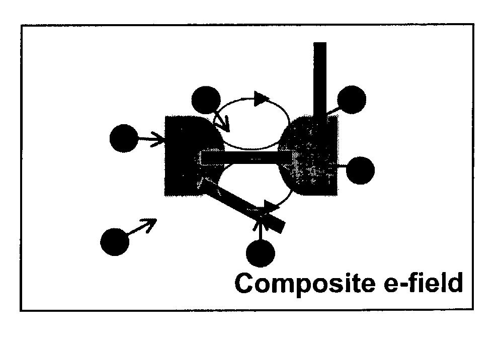
[0061]FIG. 3 and FIG. 4 illustrate a composite field tuning procedure to adjust the dc / ac ratio. A gap by flat electrodes was used for the tuning process. When only a dc electric field (Edc / Eac=∞) was applied across the gap in FIG. 3, round particles were gathered between electrodes, and a few carbon nanotubes were attracted and randomly distributed [FIG. 3(a)]. When the ratio was 1.22, more CNTs were attracted with fewer round particles gathered in the gap [FIG. 3(b)]. Although some CNTs were arrayed periodically, others were randomly placed without orientation.

example 1b

[0062]When only an ac field was applied (EDC / EAC=0), particles were rarely gathered and a few CNTs were attracted [FIG. 3(c)]. A few CNTs were attached together and the CNTs whose length was shorter than the gap size were attached to either side of the electrodes.

example 1c

[0063]FIG. 3 shows the cases when the ratio, EDC / EAC is between 0 and 1. CNTs were periodically deposited in these cases. This periodicity is attributed to the periodic hydrodynamic flow created by dc component of the electric field. As the ratio decreased, i.e., as ac component becomes stronger, the period between deposited CNTs became larger with the decreasing number of deposited particles.


PUM

PropertyMeasurementUnit
diameteraaaaaaaaaa
diametersaaaaaaaaaa
distanceaaaaaaaaaa

Abstract

Deposition of individual carbon nanotubes using a combined ac and dc composite field, and a circuit apparatus for use therewith.

Description

[0001]This application claims priority benefit from provisional application Ser. No. 60 / 376,704 filed on Apr. 30, 2002, the entirety of which is incorporated herein by reference.BACKGROUND OF INVENTION[0002]Since their discovery in 1991 (S. Iijima, Helical Microtubules of Graphite Carbon, Nature, 354 (1994) 56-58), CNTs have been investigated for many applications due to their unique and useful characteristics. A CNT can be considered as graphene sheets composed of fullerene structure of carbon atoms rolled up to form a tube shape. Multi-walled CNTs (MWCNTs) are typically on the order of a few micrometers long with a diameter up to one hundred nanometers. In case of single-walled CNTs (SWCNTs), diameters less than a few nanometers and lengths over a few hundred nanometers are common. CNTs are considered promising electro- and mechanical components due to high aspect ratio and a high mechanical strength with a ˜Tpa order of Young's modulus (D. Qian, G. J. Wagner, W. K. Liu, M. Yu, an...

Claims


Application Information

Patent Timeline
Patent Type & Authority Patents(United States)
IPC IPC(8): C25D13/10
CPCC25D13/04C25D13/12C25D13/18C25D13/20
Inventor LEE, JUNGHOONCHUNG, JAEHYUN
Owner NORTHWESTERN UNIV
Why Eureka
Try Eureka