
Reflective chiral-nematic liquid crystal display with broadband reflection

a liquid crystal display and broadband reflection technology, applied in liquid crystal compositions, instruments, chemistry apparatus and processes, etc., can solve the problems of relatively low contrast ratio, inability to teach methods for obtaining a broadband reflection display having a more neutral appearance, and inability to teach methods to improve display contrast, etc., to achieve the effect of improving neutral color

Inactive Publication Date: 2008-06-03
IRIS OPTRONICS CO LTD
View PDF8 Cites 9 Cited by
  • Summary
  • Abstract
  • Description
  • Claims
  • Application Information

AI Technical Summary

Benefits of technology

"The invention is about a display that produces better neutral colors when the liquid crystal is in the bright state. It also improves the viewing angle and expands the range of colors it can reflect. This is achieved by using an imaging layer made of a mixture of different types of liquid-crystal material that reflect in different parts of the visible spectrum. The result is a more accurate and accurate representation of colors."

Problems solved by technology

However, they disclose the spectrum of only a single CLC material with peak reflectivity of 564 nm and do not teach methods for obtaining a broadband reflecting display having a more neutral appearance.
Furthermore, although they note that the domain structure of the dispersed system in the focal conic state scatters light uniformly over the visible portion of the spectrum with the back scattered intensity gradually increasing at lower wavelengths, they do not specifically teach methods to improve contrast of the display.
Stephenson does mention that the polymer-dispersed liquid crystals have good off-axis reflectivity but does not teach how this property is to be used to create more neutral looking displays with improved viewing angle dependence.
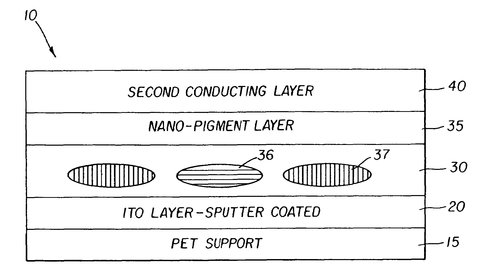
However, Applicants have determined that using an imaging layer having substantially more than a monolayer of domains (as shown by the enlarged portion of FIG. 1 results in relatively low contrast ratios.

Method used


Image

  • Reflective chiral-nematic liquid crystal display with broadband reflection
  • Reflective chiral-nematic liquid crystal display with broadband reflection
  • Reflective chiral-nematic liquid crystal display with broadband reflection

Examples


example 1

[0060]This example illustrates the influence of laydown of the liquid-crystal (“LC”) material on backscattering from the focal conic state and contrast of the display.

[0061]For 10 μm droplets, full monolayer coverage can be expected at a laydown of about 6.5 g / m2 (600 mg / ft2) of the liquid-crystal composition or a wet coverage of 80.7 cm3 / m2 (7.5 cm3 / ft2) if the coating composition is made up of 8% the liquid-crystal material and 5% gelatin by weight. An amount in slight excess of this will still constitute a substantial monolayer, well below a bi-layer of domains.

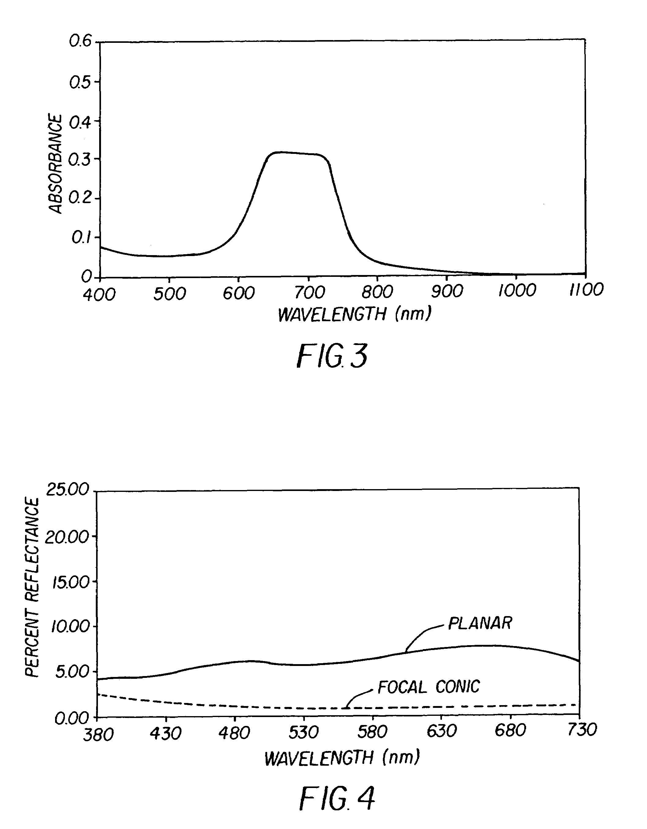
[0062]Chiral nematic compositions with center wavelengths of reflection at 470 and 690 nm were prepared by adding the appropriate amount of a high-twist chiral dopant to the nematic host mixture BL087 obtained from Merck, Darmstadt, Germany. The compositions were evaluated by placing a small amount on a glass slide with a cover slip. The “absorption” spectra were then obtained on a standard spectrophotometer. The spectrum ...

example 2

[0067]This example illustrates fabrication of a broadband bi-stable display with high contrast ratio. Consumers find such displays visually pleasing because of their more neutral appearance.

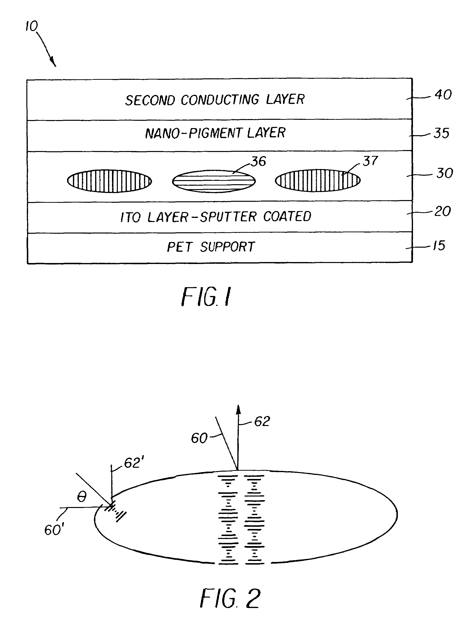
[0068]It should be noted that the spectrum of the LC material in the planar state in a coated droplet is much broader than the spectrum of the material between glass slides. For example, the red reflecting LC material shown in FIG. 3 has a spectrum as shown in FIG. 6 when it is in a coated droplet because of the elliptical shape of the droplet. As shown previously in FIG. 2, measurable reflectance for a coated droplet may be obtained in this case at lower wavelengths because of the Bragg reflection condition at the curved boundary of a droplet. The wavelength of maximum reflection λmax is given by λmax=np cos θ where n is the average refractive index of the LC material and p is its pitch. Note that cos θ decreases as θ increases. In other words, a red reflecting LC composition may actually reflec...


PUM

PropertyMeasurementUnit
peak reflected wavelengthaaaaaaaaaa
diameteraaaaaaaaaa

Abstract

A display sheet comprising a substrate carrying layers of material; including a polymer-dispersed chiral-nematic liquid-crystal layer having a first high reflection state within the visible light spectrum and a second less-reflective state in said spectrum, said states being changeable by an electric field, which states can be maintained in the absence of an electric field; a first transparent conductor disposed over said polymer-dispersed chiral-nematic liquid-crystal layer; and a second conductor, wherein said imaging layer is substantially a monolayer of said domains comprises a mixture of at least two differently reflecting liquid crystal materials, in which the λ maximums of the two materials are separated by 100 to 250 nm.

Description

FIELD OF THE INVENTION[0001]The present invention relates to a display sheet having a chiral-nematic liquid-crystal layer that can change states, a relatively lighter (brighter) state and a relatively darker state, to provide a viewable image. In particular, the invention relates to a display sheet in which the relatively lighter state exhibits a more neutral appearance based on a broadband reflection.BACKGROUND OF THE INVENTION[0002]Bi-stable reflective displays based on PDLC are known. A polymer dispersed liquid crystal (PDLC) system contains droplets of liquid crystal material dispersed in a polymer matrix. Such systems are known in the art and have been disclosed by Doane et al. (Applied Physics Letters 48, 269 (1986)), West et al. (Applied Physics Letters 63, 1471(1993)) and by Stephenson (U.S. Pat. No. 6,359,673). The PDLC may be used to create passive matrix displays on flexible substrates. See also U.S. Pat. No. 6,061,107 to Yang et al., incorporated by reference. Chiral-nem...

Claims


Application Information

Patent Timeline
Patent Type & Authority Patents(United States)
IPC IPC(8): G02F1/1333G02F1/1334G02F1/137
CPCG02F1/1334G02F1/13718G02F1/133305G02F2203/34
Inventor CHARI, KRISHNANRANKIN, JR., CHARLES M.
Owner IRIS OPTRONICS CO LTD
Learn More