Voltage multiplier with charge recovery

Active Publication Date: 2008-06-03
VIVO MOBILE COMM CO LTD
View PDF21 Cites 44 Cited by
  • Summary
  • Abstract
  • Description
  • Claims
  • Application Information

AI Technical Summary

Benefits of technology

[0024]The increased battery life of the invented circuit is of importance for handheld and other small electronic devices. An advantage is t

Problems solved by technology

Inductive and piezoelectric voltage multipliers are for size and weight reasons not practical for high voltage generation in handheld terminals.
Although widely used in high voltage high power pulse applications, this kind of store and stack system has drawbacks, especially when a steady level high voltage is needed, because the stack will discharge and the output voltage will drop after the initial pulse.
When the high voltage pulse is to be terminated, the charge on the output capacitor is normally discharged to ground on the falling edge of the pulse and

Method used


Image

  • Voltage multiplier with charge recovery
  • Voltage multiplier with charge recovery
  • Voltage multiplier with charge recovery

Examples


Embodiment Construction

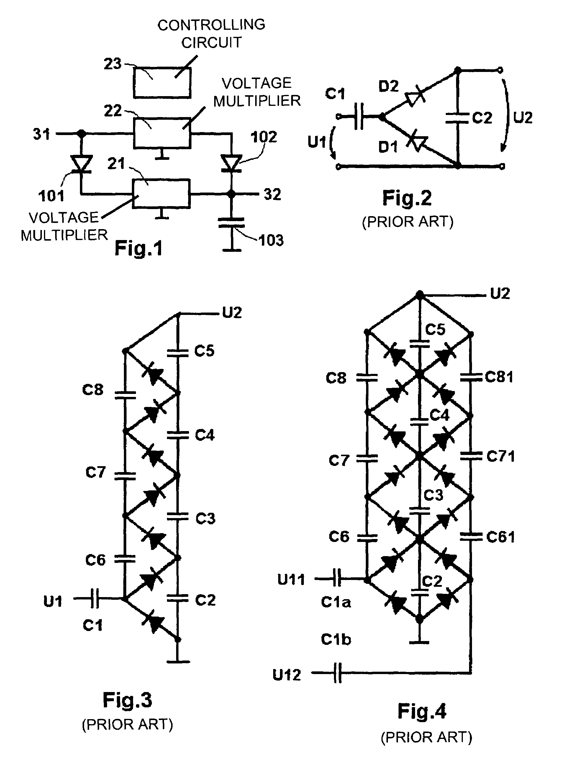
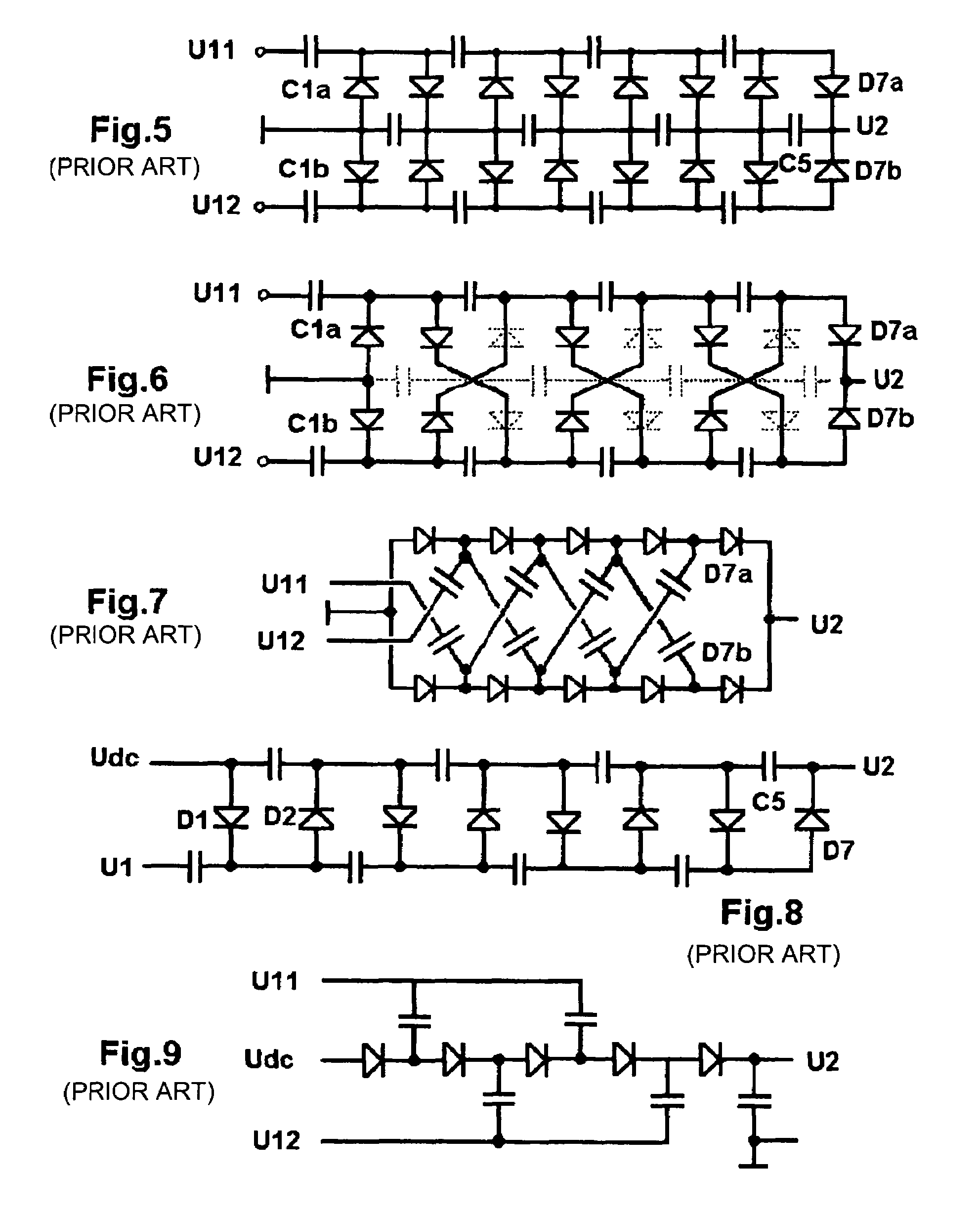
[0037]FIGS. 2 to 9 have already been explained above and examplifies the known circuits that can be used as the second multiplier 22 of the invention. This multiplier 22 can have the configuration and number of stages that is most suitable to be used with the operational load and the operational use of the multiplier 21. FIG. 10 illustrates the operation of a parallel / series switched capacitor multiplier that can be used as the first multiplier 21 of the invention. The operation of this circuit has also already been explained, but it its should be pointed out that the number of capacitors C1, C2 . . . Cn can vary from two to any number n.

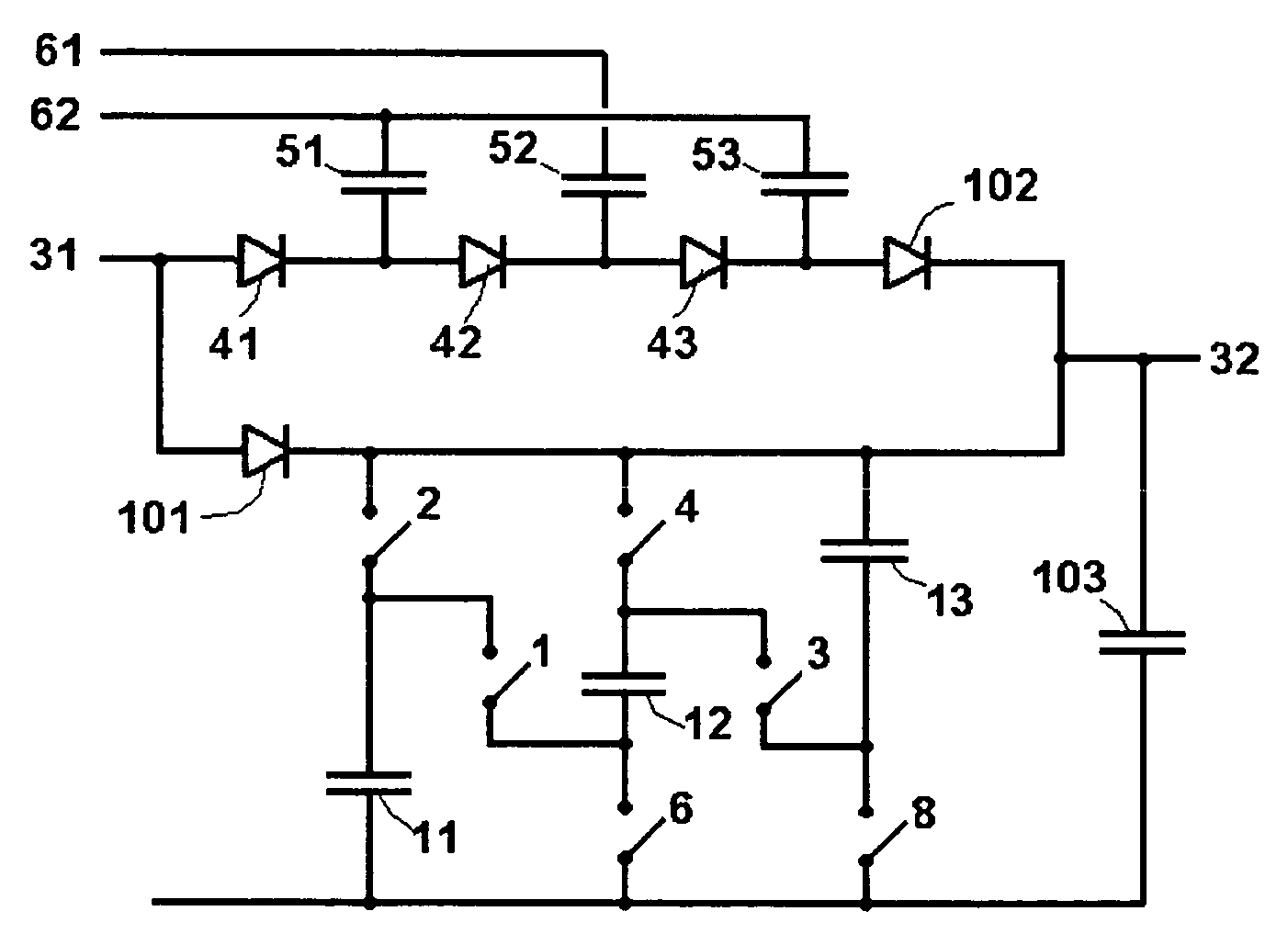
[0038]The invention is best explained with reference to the block diagram shown in FIG. 1 and the example circuit depicted in FIG. 11, which shows a voltage multiplier for generating voltage pulses, up to 100 V, for displays, non-volatile memories and corresponding units in small electronic devices, such as handheld telecommunication or correspondin...


PUM


Abstract

Capacitive voltage multiplier for generating voltage pulses, preferably up to 100 V, that are higher than the supply voltage for displays, non-volatile memories and corresponding units especially in small electronic devices, such as handheld telecommunication terminals or corresponding devices, wherein the multiplier comprises a switching capacitor circuit (21) provided with capacitors and switches for charging the capacitors in parallel and discharging them in series in order to deliver a high voltage pulse. The multiplier further comprises a diode chain circuit (22) consisting of a diode-chain and pumping capacitors for delivering high voltage current. The inventive system allows the output high voltage to be switched on and held with little longtime drop and with small switching losses and able to supply a load current without significant ripple. Additionally switching the high voltage on and off does not result in efficiency loss.

Description

FIELD OF INVENTION[0001]The present invention relates to voltage multipliers for generating voltage pulses that are higher than the supply voltage, and more particularly to capacitive voltage multipliers for generating voltage pulses, up to 100 V, for displays, non-volatile memories and corresponding units in small electronic devices, such as handheld telecommunication or corresponding terminals.BACKGROUND OF THE INVENTION[0002]Voltage multiplying circuits use either capacitive or inductive phenomena to step up an input voltage. Even the recently introduced piezoelectric step-up transformers use piezo-capacitive phenomena to generate stepped up output voltage. Inductive and piezoelectric voltage multipliers are for size and weight reasons not practical for high voltage generation in handheld terminals. For use with integrated circuitry capacitive mulipliers are the preferred choice.[0003]Basically two types of on-chip circuits are known that generate pulses higher than the supply vo...

Claims


Application Information

Patent Timeline
IPC IPC(8): H02M3/18H02M7/00H02M7/19H02M3/07
CPCH02M3/07H03K3/57
Inventor BUCHMANN, MICHAEL
Owner VIVO MOBILE COMM CO LTD
Why Eureka
Try Eureka