
Nested strong loader apparatus and method

a loader and loader technology, applied in the field of cryptographic systems and methods, can solve the problems of limiting the market of cryptographic policies, affecting the quality of cryptographic software, and reducing so as to reduce the probability of their being decoded insufficient length and complexity

Inactive Publication Date: 2008-06-03
EMC IP HLDG CO LLC
View PDF32 Cites 14 Cited by
  • Summary
  • Abstract
  • Description
  • Claims
  • Application Information

AI Technical Summary

Benefits of technology

[0042]It is another object of the invention to provide an apparatus and method for dynamic loading of the plurality of individual and distinct modular cryptography modules into the base executable in a manner to prevent substitution, modification, extension, or misuse of algorithms implementable by the modules and whereby each of the independent slots may have independent mechanisms for authorization of the modular cryptography modules.
[0058]Another feature of an apparatus and method in accordance with the invention may include cryptographic wrapping of keys. That is, wrapping may be thought of as tamper proofing (authentication) and encrypting (secrecy protection) a key. Prior art systems' keys may be simply bit strings of sufficient length and complexity to reduce the probability of their being deciphered.

Problems solved by technology

Moreover, these policies are undergoing constant change periodically.
Cryptographic policies may limit markets.
Thus, generalized software development standardization of software, and the like may become difficult for software vendors.
Moreover, users have difficulties attendant with supporting limited installed bases of specialized software.
In addition to restrictions on allowable algorithms, cryptographic use policies may also place constraints on the use and strength keys associated with those algorithms.
Users have previously demonstrated that networks may be subject to attack by spoofing of network control packets.
By such spoofing, users may obtain unauthorized privileges on a network server.
Proprietary encryption methodologies have been consistently broken, given enough time and attention by interested hackers.
Also, certain algorithms are the subject of patent applications which may cloud their broadly based use.
However, software manufacturers using this technology typically require that a third-party vendor send its product to the principal software manufacturer for integration.
Also, export restrictions exist for encryption technology.
Moreover creating “cryptography with a hole” is undesirable for several reasons, including export and import restrictions.
A great escalation of the difficulty of such introduction, without creating numerous, individually customized software packages, is a major need today, although not necessarily well recognized.
Key escrow systems may be easily provided in software, but integrity and assurance remain difficult.
Using only software, reliable key escrow may be impossible, in the absence of very high assurance.
Under any circumstances, software offers few protections when compared with hardware solutions.
Meanwhile such solutions as key escrow do not receive ready customer acceptance in U.S. markets, particularly where a government is an escrow agent.
Currently, no provision exists for allowing such customization in a controlled, authenticable environment.
That is, what is needed are modules that may be used to limit the capabilities of cryptographic applications without proliferating individual customized software products that may become very difficult to maintain, upgrade, support, and the like.

Method used


Image

  • Nested strong loader apparatus and method
  • Nested strong loader apparatus and method
  • Nested strong loader apparatus and method

Examples


Embodiment Construction

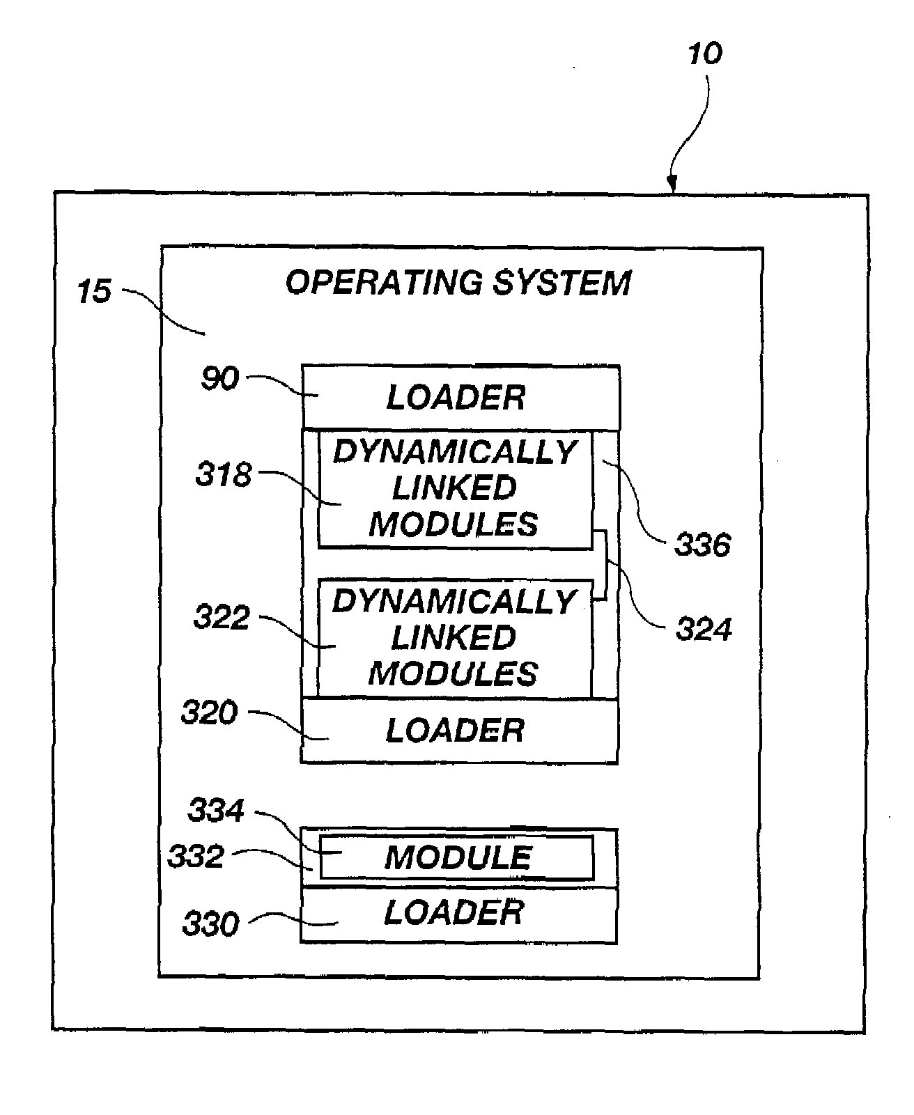
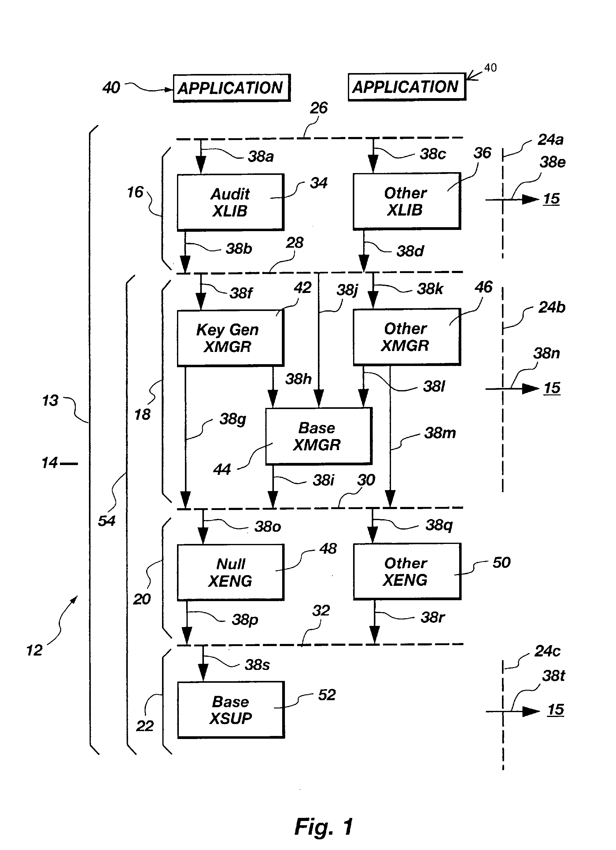
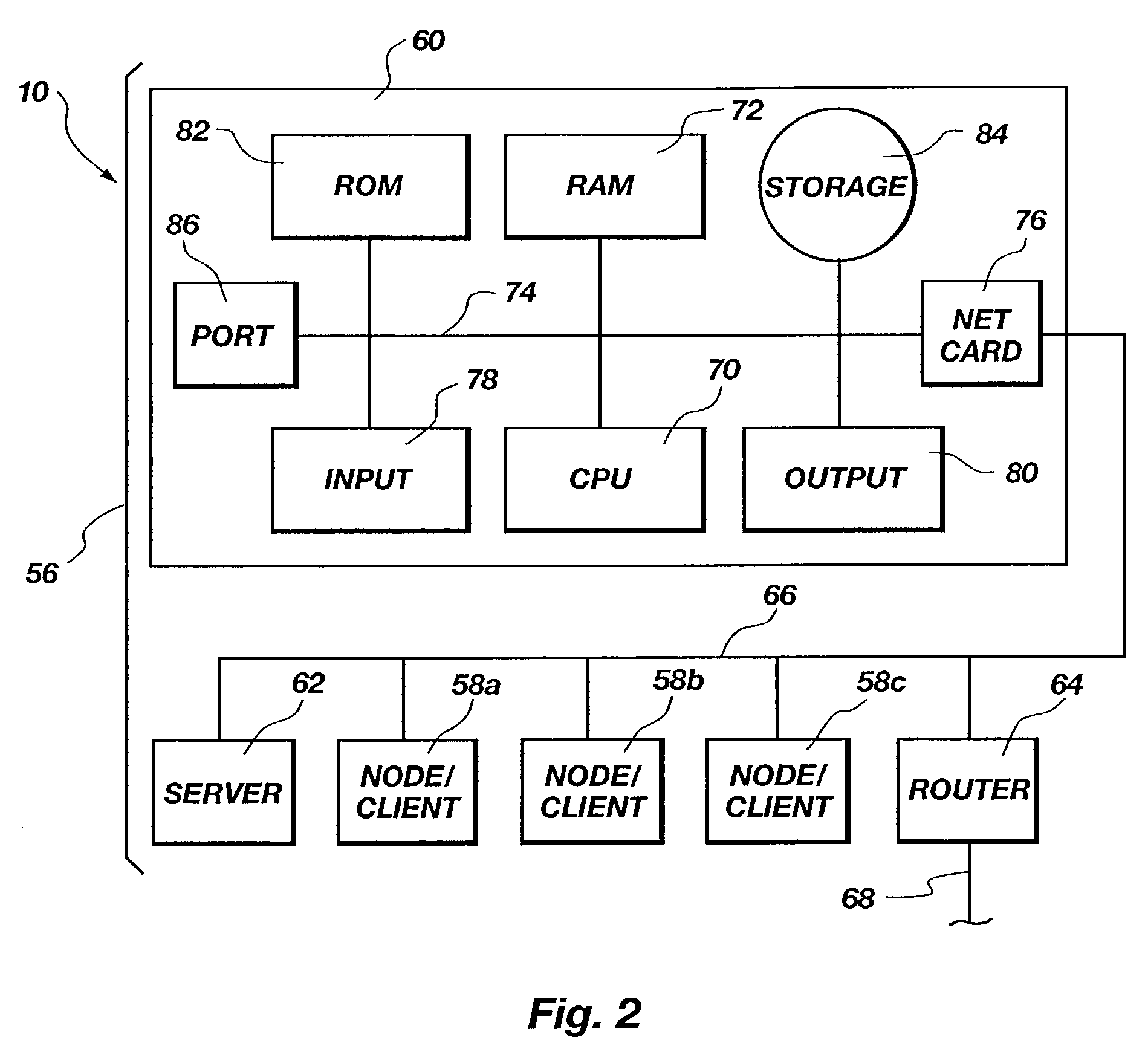
[0076]It will be readily understood that the components of the present invention, as generally described and illustrated in the Figures herein, could be arranged and designed in a wide variety of different configurations. Thus, the following more detailed description of the embodiments of the system and method of the present invention, as represented in FIGS. 1 through 6, is not intended to limit the scope of the invention, as claimed, but it is merely representative of certain presently preferred embodiments of the invention.

[0077]The presently preferred embodiments of the invention will be best understood by reference to the drawings, wherein like parts are designated by like numerals throughout. Reference numerals having trailing letters may be used to represent specific individual items (e.g., instantiations) of a generic item associated with the reference numeral. Thus, a number 156a, for example, may be the same generic item as number 156f, but may result from a different vers...


PUM


Abstract

An apparatus and method provides one or more controlled, dynamically loaded, modular, cryptographic fillers. Fillers may be loaded by a single loader, multiple independent loaders, or nested loaders. Loaders may be adapted to load other loaders, within cryptographic controls extant and applicable thereto. Integration into a base executable having one or more slots, minimizes, controls, and links the interface between the fillers and base executables. The filler may itself operate recursively to load another filler in nested operations, whether or not the fillers are in nested relation to one another. An ability of any filler to be loaded may be controlled by the base executable verifying the integrity, authorization, or both for any filler. The base executable may rely on an integrated loader to control loading and linking of fillers and submodules. A policy may limit each module function, access, and potential for modification or substitution. Dynamically loaded modules (loaders, other fillers, and submodules thereof), typically represent a relatively small portion of the overall coding required by the base executable, and may provide strong controls limiting integration by providing access that is nested, layered, or both between modules excluding direct access to or by them from the base executable or supported applications.

Description

RELATED APPLICATIONS[0001]This application is a continuation of U.S. Ser. No. 09 / 274,532 filed Mar. 23, 1999 now U.S. Pat. No. 6,532,451 which is a Continuation-In-Part of, and claims priority to, U.S. Provisional Patent Application Ser. No. 60 / 079,133, filed on Mar. 23, 1998, the specifications of which are incorporated herein by reference.BACKGROUND[0002]1. The Field of the Invention[0003]The present invention relates to cryptographic systems and methodology. More particularly, the present invention relates to novel apparatus systems and the capability of hosting a plurality of individual modularized methods for allowing encrypting applications within a single use application operating on a computer and to separately control the access, use, and authorization of each of the individual encrypting applications.[0004]2. The Background Art[0005]Encryption is a technology dating from ancient times. In modern times, encryption of military communications has been common. However, since t...

Claims


Application Information

Patent Timeline
IPC IPC(8): G06F11/30G06F12/14H04L9/32H04L9/00H04L9/14G06F21/00H04L29/06
CPCG06F21/602G06Q20/3674G06Q20/383G06Q20/401H04L63/04H04L63/0428
Inventor SCHELL, ROGER R.KINGDON, KEVIN W.BERSON, THOMAS A.
Owner EMC IP HLDG CO LLC
Learn More