Impact power tool

a power tool and rubber ring technology, applied in the field of impact power tools, can solve the problems of difficult to provide the hardness of the rubber ring, and achieve the effect of lessening the impact for

Active Publication Date: 2008-06-10
MAKITA CORP
View PDF33 Cites 64 Cited by
  • Summary
  • Abstract
  • Description
  • Claims
  • Application Information

AI Technical Summary

Benefits of technology

[0006]Accordingly, it is an object of the invention to provide an improved technique for lessening an impact force caused by rebound of a tool bit after the striking movement of the tool bit.
[0009]During hammering operation, the hammer actuating member is caused to rebound by receiving the reaction force of the workpiece after striking movement. According to the invention, with the construction in which the reaction force is transmitted from the hammer actuating member to the weight located in the reaction force transmitting position, the reaction force can be approximately 100% transmitted. In other words, the reaction force is transmitted by exchange of momentum between the hammer actuating member and the weight. By this transmission of the reaction force, the weight is caused to move rearward in the direction of action of the reaction force. The rearward moving weight elastically deforms the elastic element and absorbed by such elastic deformation. As a result, vibration of the impact power tool can be reduced.
[0010]Further, according to the invention, the control member prevents an elastic force of the elastic element from acting upon the weight forward beyond the reaction force transmitting position. As a result of such control member, when the user applies a pressing force forward to the tool body during striking movement, unnecessary force for holding the hammer actuating member is not required even with a provision of the elastic element for absorbing the reaction force. Unlike the construction such as an idle driving prevention mechanism in which a forward spring force normally acts upon the hammer actuating member, an efficient mechanism can be realized which can absorb a reaction force and in which the elastic force for absorbing the reaction force has no adverse effect when the user presses the hammer actuating member against the workpiece to place the hammer actuating member in a striking position.

Problems solved by technology

It is difficult to provide the rubber ring with a hardness that satisfies the both functional requirements.

Method used


Image

  • Impact power tool
  • Impact power tool
  • Impact power tool

Examples


first representative embodiment

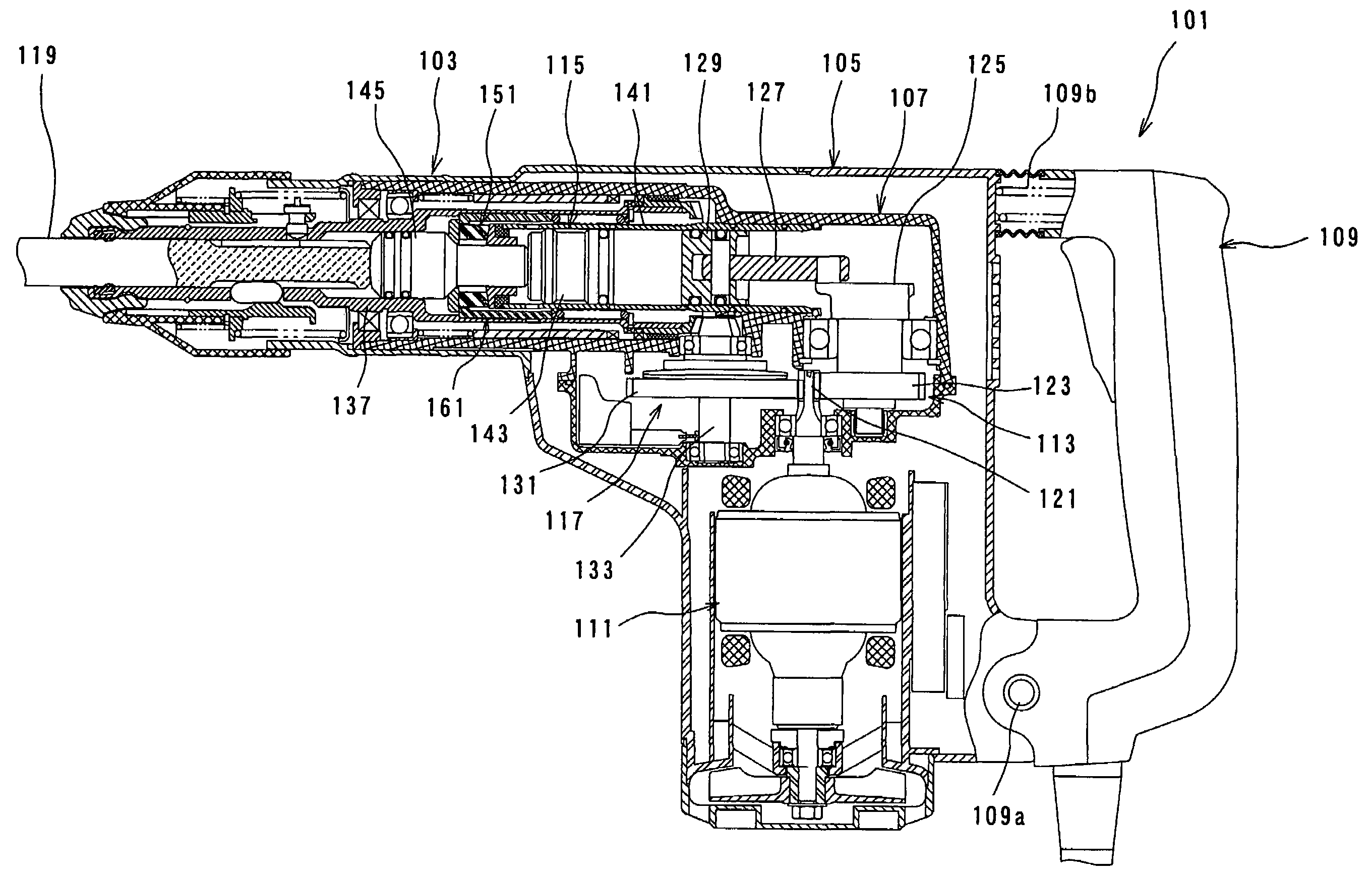
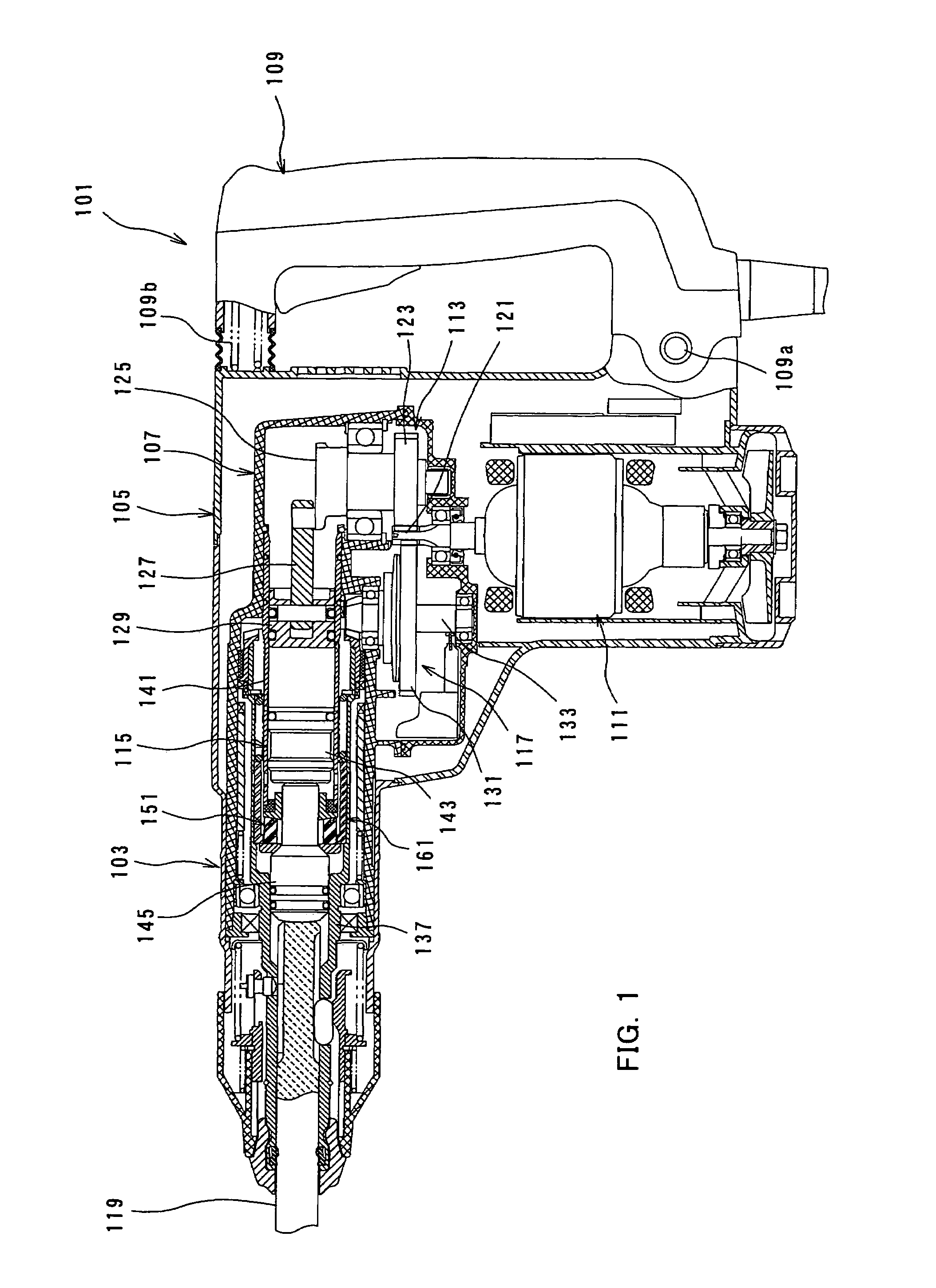
[0032]A first representative embodiment of the present invention is now described with reference to FIGS. 1 to 5. FIG. 1 is a sectional side view showing an entire electric hammer drill 101 as a first representative embodiment of the impact power tool according to the invention, under loaded conditions in which a hammer bit is pressed against a workpiece.

[0033]As shown in FIG. 1, the hammer drill 101 includes a body 103, a hammer bit 119 detachably coupled to the tip end region (on the left side as viewed in FIG. 1) of the body 103 via a tool holder 137, and a handgrip 109 that is held by a user and connected to the rear end region (on the right side as viewed in FIG. 1) of the body 103. The body 103 is a feature that corresponds to the “tool body” according to the present invention. The hammer bit 119 is held by the tool holder 137 such that it is allowed to reciprocate with respect to the tool holder 137 in its axial direction and prevented from rotating with respect to the tool h...

second representative embodiment

[0055]Now, a second representative embodiment of the present invention is described with reference to FIGS. 6 to 8. In the second embodiment, the reaction force (rebound) caused during the striking movement is transmitted from the hammer bit 119 to the impact damper161 and except for this point, the second representative embodiment has the same construction as the first embodiment. Thus, components and elements in the second embodiment which are substantially identical to those in the first embodiment are given like numerals as in the first embodiment and is not described or only briefly described.

[0056]In this embodiment, the impact bolt 145 has a large-diameter portion 145a in the middle in its axial direction and small-diameter portions 145b, 145d on the rear and front sides of the large-diameter portion 145a. Further, a tapered portion 145c is formed in the boundary region between the rear small-diameter portion 145b and the large-diameter portion 145a. The tapered surface of th...

third representative embodiment

[0065]A third representative embodiment of the present invention is now described with reference to FIGS. 9 to 13. In the third embodiment, an idle driving prevention mechanism (shown in drawings with a reference number 181) is further adapted and except for this point, the third representative embodiment has the same construction as the first embodiment. Thus, components and elements in the second embodiment which are substantially identical to those in the first embodiment are given like numerals as in the first embodiment and is not described or only briefly described.

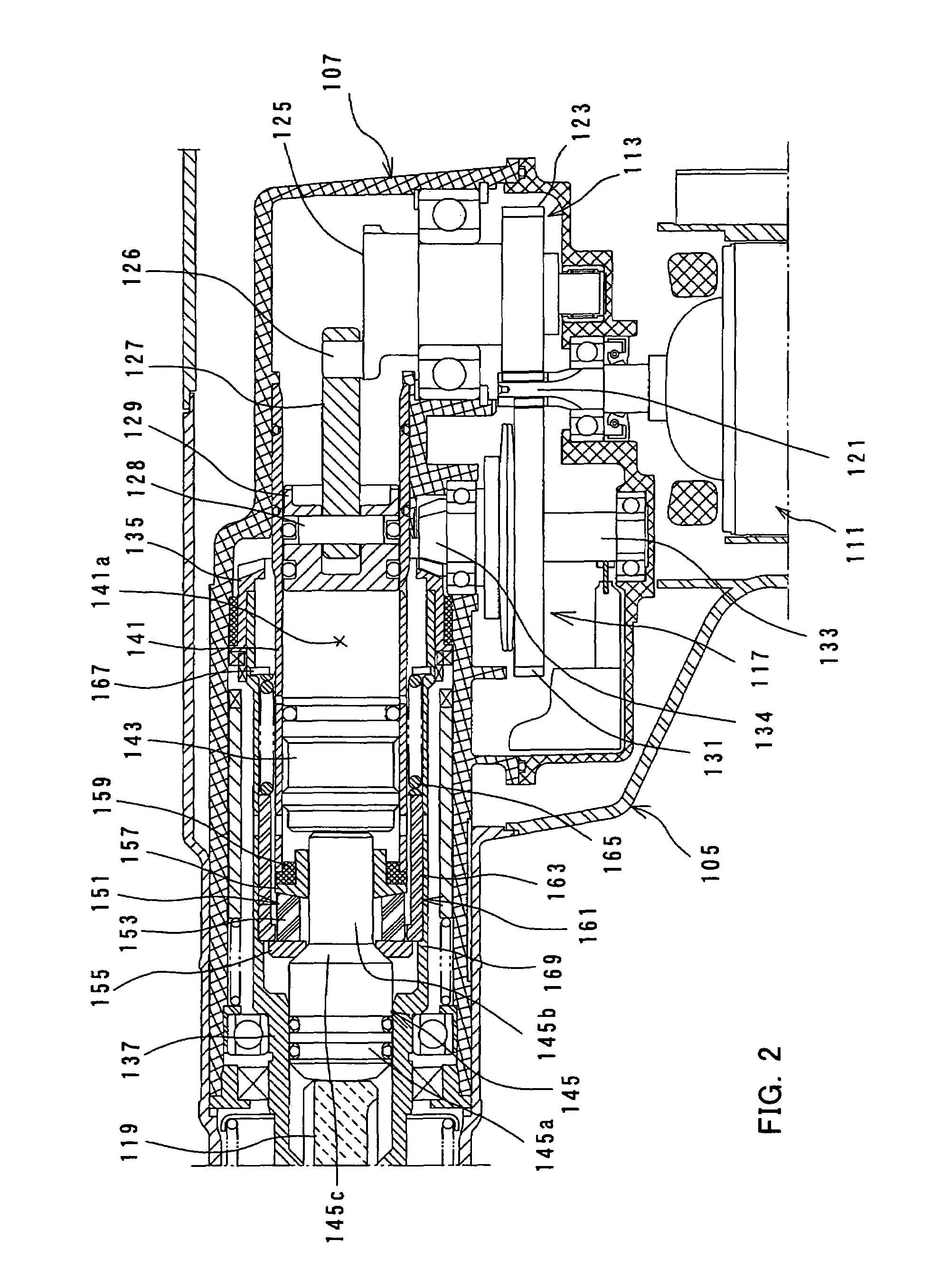
[0066]According to this embodiment, the hammer drill 101 includes an idle driving prevention mechanism 181 that serves to prevent striking movement of the hammer bit 119 when the driving motor 111 is driven under unloaded conditions in which the hammer bit 119 is not pushed rearward. The air chamber 141a that serves to drive the striker 143 via the action of an air spring is in communication with the outside via an ...


PUM

PropertyMeasurementUnit
weightaaaaaaaaaa
elastic forceaaaaaaaaaa
reaction forceaaaaaaaaaa

Abstract

It is an object of the invention to provide an improved technique for lessening an impact force caused by rebound of a tool bit after the striking movement of the tool bit. Representative impact power tool (101) includes a tool body (103), a hammer actuating member (119, 145), a driving mechanism (113, 115), a weight (163) and an elastic element (165). A reaction force that the hammer actuating member receives from the workpiece when performing a hammering operation is transmitted from the hammer actuating member to the weight (163) and then, the weight (163) is caused to move rearward to push the elastic element (165). As a result, the reaction force can be absorbed by the elastic element (165). The elastic force of the elastic element (165) is prevented from acting upon the weight (163) forward beyond the reaction force transmitting position.

Description

BACKGROUND OF THE INVENTION[0001]1. Field of the Invention[0002]The present invention relates to an impact power tool for performing a linear hammering operation on a workpiece and more particularly, to a technique for cushioning a reaction force received from the workpiece during hammering operation.[0003]2. Description of the Related Art[0004]Japanese non-examined laid-open Patent Publication No. 8-318342 discloses a technique for cushioning an impact force caused by rebound of a tool bit after an striking movement within a hammer drill. In the known hammer drill, a rubber ring (cushion member) is disposed between the axial end surface of a cylinder on the body side and an intermediate element in the form of an impact bolt which strikes the tool bit. When the tool bit receives a reaction force from the workpiece and rebounds after striking movement of the tool bit, the impact bolt collides with the rubber ring. At this time, the rubber ring cushions the impact force by elastic def...

Claims


Application Information

Patent Timeline
Patent Type & Authority Patents(United States)
IPC IPC(8): B25D11/00B25D17/24
CPCB25D16/00B25D17/06B25D17/24B25D2211/003B25D2211/068B25D2217/0019B25D2217/0092B25D2250/035B25D2250/095B25D2250/245B25D2250/371B25D2250/391
Inventor AOKI, YONOSUKE
Owner MAKITA CORP
Why Eureka
Try Eureka