
Multi-beam klystron apparatus

a klystron and beam technology, applied in the direction of cathode-ray/electron-beam tube circuit elements, instruments, beam deviation/focusing by electric/magnetic means, etc., can solve the problems of reducing output conversion efficiency, curved lines of magnetic force, electron beams

Active Publication Date: 2008-06-10
CANON ELECTRON TUBES & DEVICES CO LTD
View PDF9 Cites 17 Cited by
  • Summary
  • Abstract
  • Description
  • Claims
  • Application Information

AI Technical Summary

Benefits of technology

This configuration enables the axial magnetic flux density to be increased near the output cavity without curving the electron beams, effectively preventing their spread and ensuring stable operation by maintaining parallel magnetic field lines.

Problems solved by technology

The method of simply increasing the radius of the drift tube, however, encounters the problem of a reduced output conversion efficiency, and therefore a method is generally employed in which the axial magnetic flux density of the focusing magnetic field is increased in the neighborhood of the output cavity.
In this multi-beam klystron apparatus, an increase in the axial magnetic flux density in the neighborhood of the output cavity to suppress the spread of the electron beam, like in the single-beam klystron apparatus, would pose the problem that the lines of magnetic force are curved and so are the electron beams.
Under this condition, the electron beam would impinge on the drift tube and therefore it is impossible to assure stable operation of the multi-beam klystron apparatus by increasing the axial magnetic flux density in the neighborhood of the output cavity.

Method used


Image

  • Multi-beam klystron apparatus
  • Multi-beam klystron apparatus
  • Multi-beam klystron apparatus

Examples


first embodiment

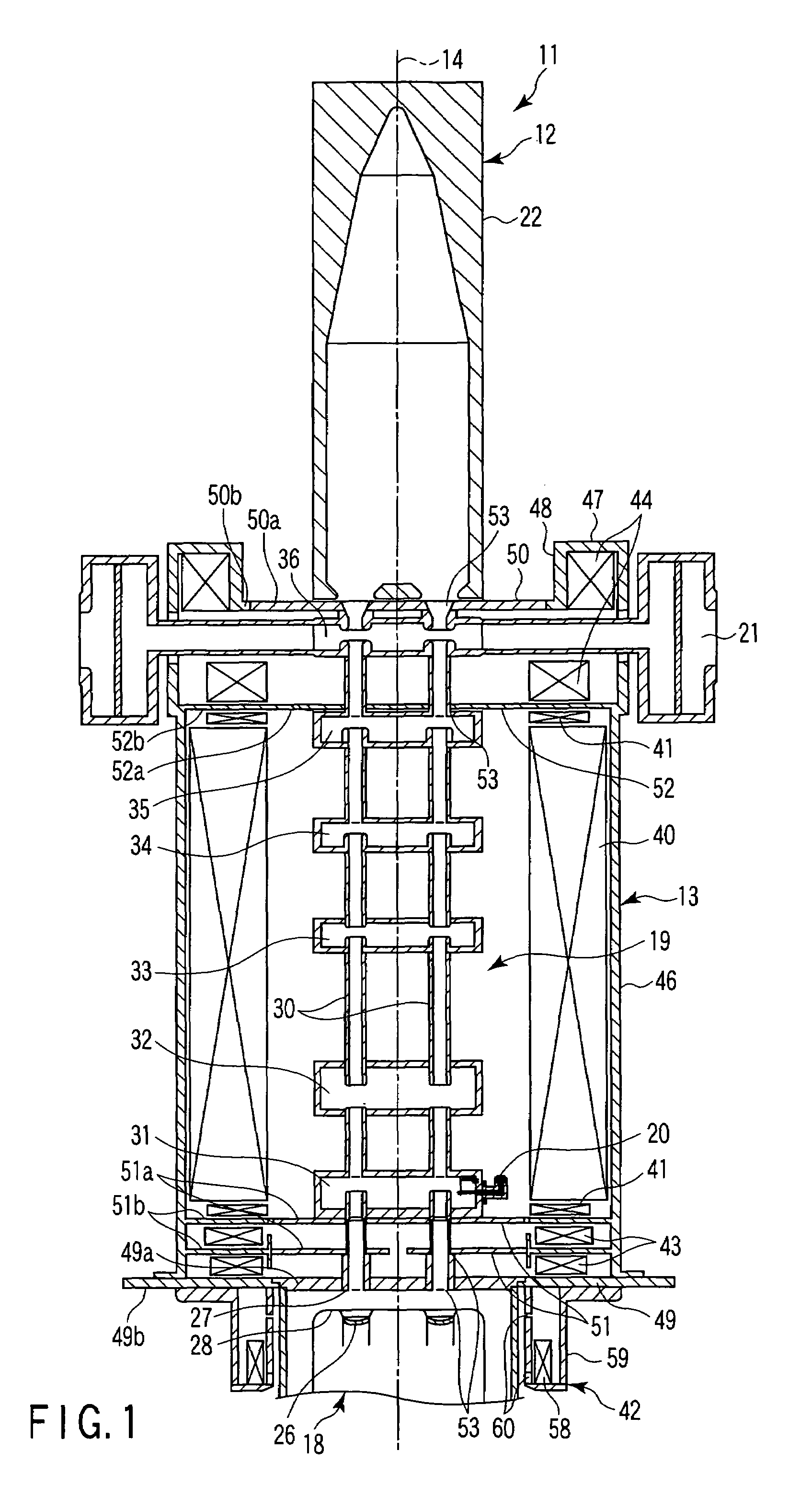
[0033]FIGS. 1 to 8 show the invention.

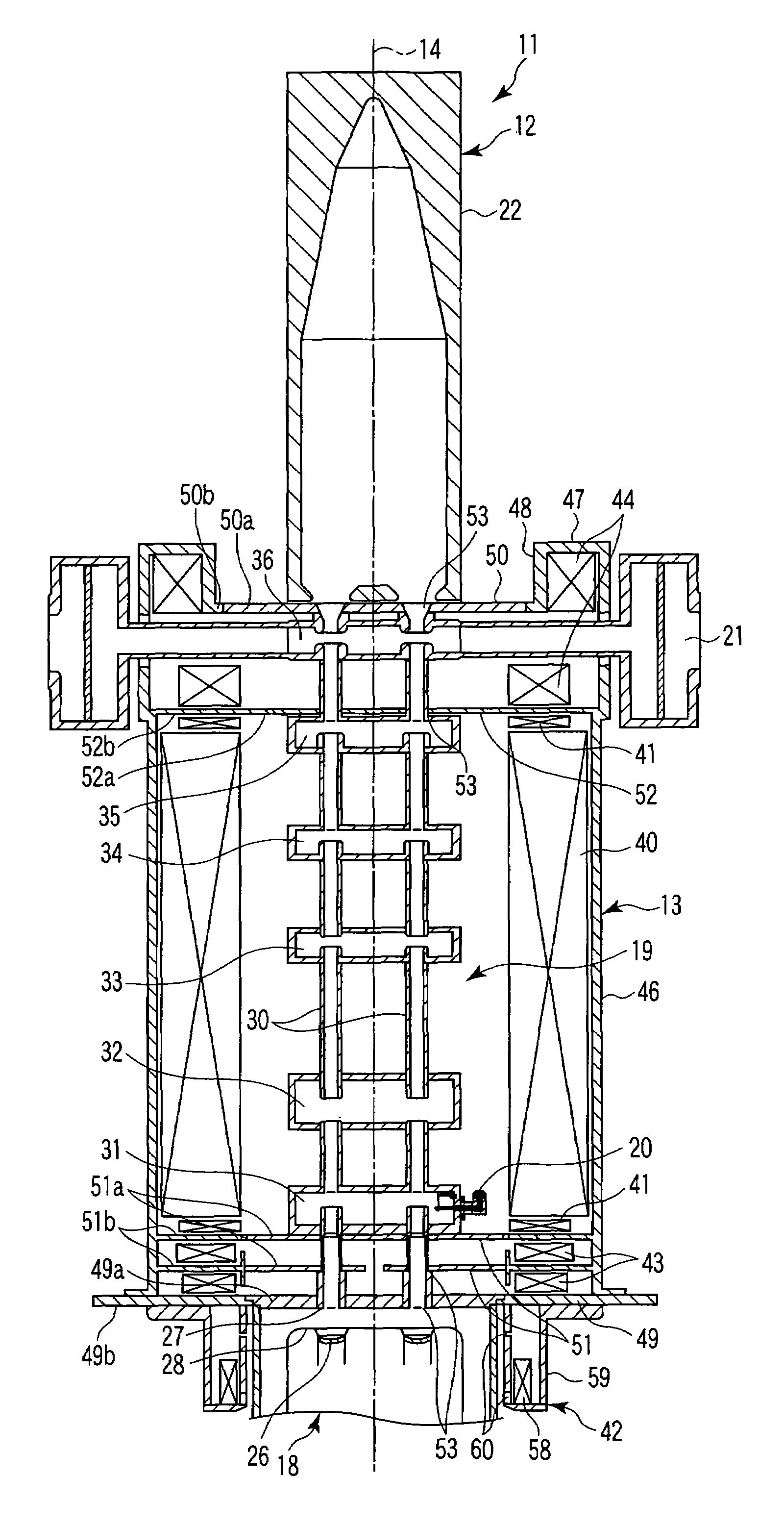
[0034]As shown in FIG. 1, a multi-beam klystron apparatus 11 includes a klystron body 12 and a focusing magnetic field unit 13. In FIG. 1, reference numeral 14 designates the center axis of the multi-beam klystron apparatus 11.

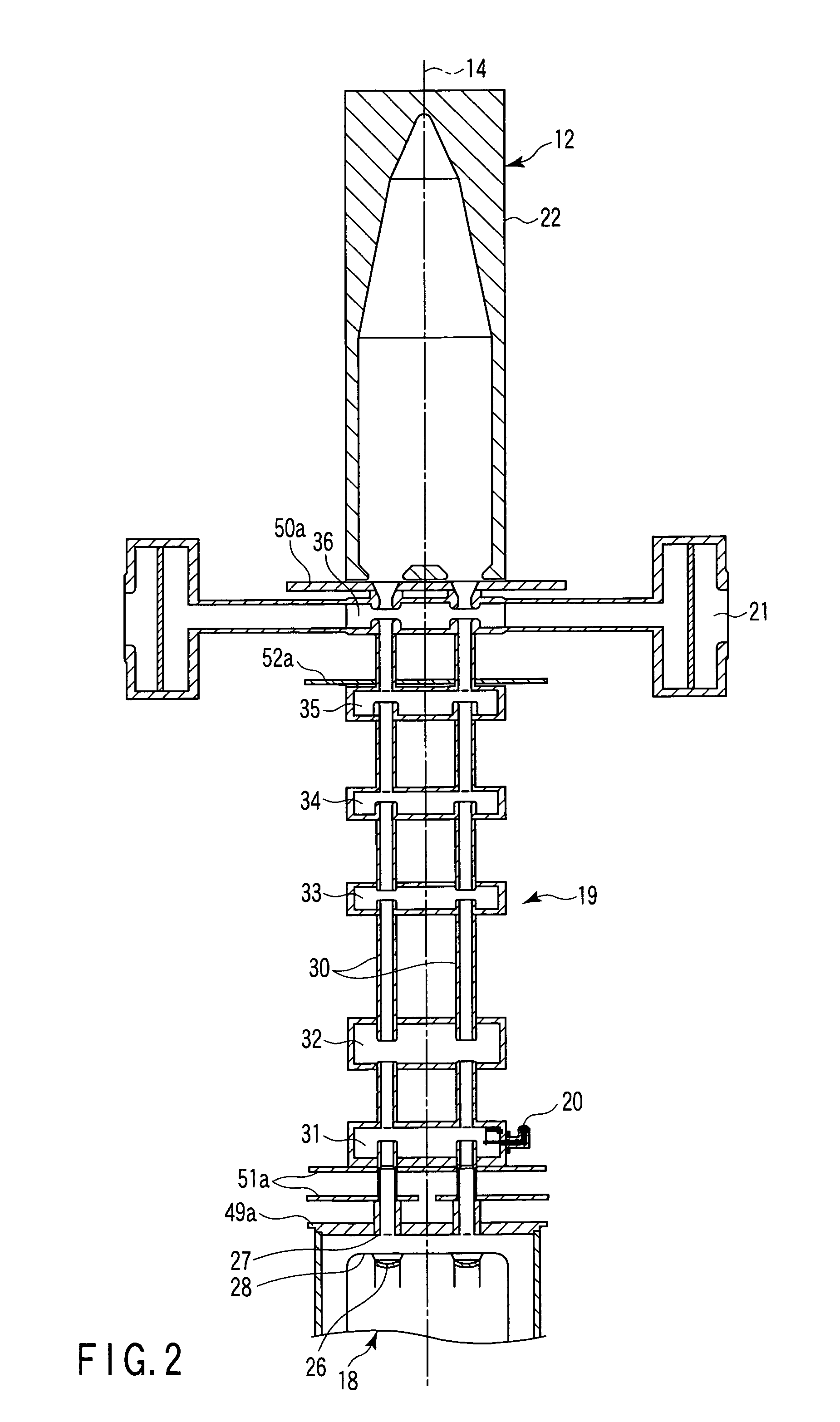
[0035]As shown in FIG. 2, the klystron body 12 includes an electron gun unit 18 for generating electron beams from a plurality of points, a radio-frequency interaction unit 19 for amplifying the radio-frequency power by the interaction between the electron beams and the radio-frequency electric field, an input unit 20 for inputting the radio-frequency power to the radio-frequency interaction unit 19, an output unit 21 for outputting the radio-frequency power from the radio-frequency interaction unit 19, and a collector unit 22 for capturing only the used electron beams having passed through the radio-frequency interaction unit 19.

[0036]The electron gun unit 18 includes a plurality of cathodes 26 arranged on the circumferen...


PUM


Abstract

A multi-beam klystron apparatus is disclosed. A radio-frequency interaction unit pole piece is arranged between a main magnetic field generator and an output-side magnetic field generator. The magnetic circuit formed in the neighborhood of an output cavity of a radio-frequency interaction unit is separated from the magnetic circuit of the main magnetic field generator by the radio-frequency interaction unit pole piece. The output-side magnetic field generator increases the axial magnetic flux density in the neighborhood of the output cavity without curving the electron beams and thus prevents the spread of the electron beams in the neighborhood of the output cavity.

Description

CROSS-REFERENCE TO RELATED APPLICATIONS[0001]This application is based upon and claims the benefit of priority from prior Japanese Patent Application No. 2005-346046, filed Nov. 30, 2005, the entire contents of which are incorporated herein by reference.BACKGROUND OF THE INVENTION[0002]1. Field of the Invention[0003]This invention relates to a multi-beam klystron apparatus for amplifying radio-frequency power.[0004]2. Description of the Related Art[0005]The conventional klystron apparatus includes an electron gun unit for generating an electron beam, an input unit for inputting radio-frequency power, a radio-frequency interaction unit for amplifying the radio-frequency power by the interaction between the electron beam and the radio-frequency electric field, an output unit for outputting the radio-frequency power from the radio-frequency interaction unit, a klystron body having a collector unit for capturing the used electron beam having passed through the radio-frequency interactio...

Claims


Application Information

Patent Timeline
Patent Type & Authority Patents(United States)
IPC IPC(8): H01J25/10G21K1/08
CPCH01J23/087H01J25/10
Inventor MIYAKE, SETSUO
Owner CANON ELECTRON TUBES & DEVICES CO LTD
Learn More