Process and device for synchronization and codegroup identification in cellular communication systems and computer program therefor

a technology of cellular communication system and codegroup, applied in the field of telecommunications systems, can solve problems such as power consumption in the future, and achieve the effects of reducing computational complexity, reducing processing circuit size and memory size, and occupying less spa

Active Publication Date: 2008-06-10
MICROELECTRONIC INNOVATIONS LLC
View PDF6 Cites 8 Cited by
  • Summary
  • Abstract
  • Description
  • Claims
  • Application Information

AI Technical Summary

Benefits of technology

[0029]Basically, the solution according to the present invention involves simplifying the processing circuits and the size of the corresponding memory, as well as reducing the computational complexity. At the same time, the solution according to the invention enables a circuit to be obtained which allows ...

Problems solved by technology

In particular, when a mobile terminal is turned on, it does not have any knowledge of the timing of the transmitting cell to which it is to be...

Method used


Image

  • Process and device for synchronization and codegroup identification in cellular communication systems and computer program therefor
  • Process and device for synchronization and codegroup identification in cellular communication systems and computer program therefor
  • Process and device for synchronization and codegroup identification in cellular communication systems and computer program therefor

Examples


first embodiment

[0041]Turning to FIG. 5, a parallel architecture for implementing the correlation section in FDD mode is now described. The received signal r is sent at the input to a first matched FIR filter 210, which includes sixteen registers and a corresponding number of output taps. The first filter 210 also receives at its input a first Golay sequence SG1 for the secondary code SSC to carry out the filtering as described above.

[0042]The signal thus filtered by first filter 210 is sent to a second filter 220, which is also an FIR filter with two hundred and forty registers and sixteen outputs. Operation of the second filter 220 is driven by an enable and stop signal ENS, which likewise operates on the first filter 210, for enabling storage in the filters of the received signal r for the subsequent operation of correlation with the secondary codes SSC.

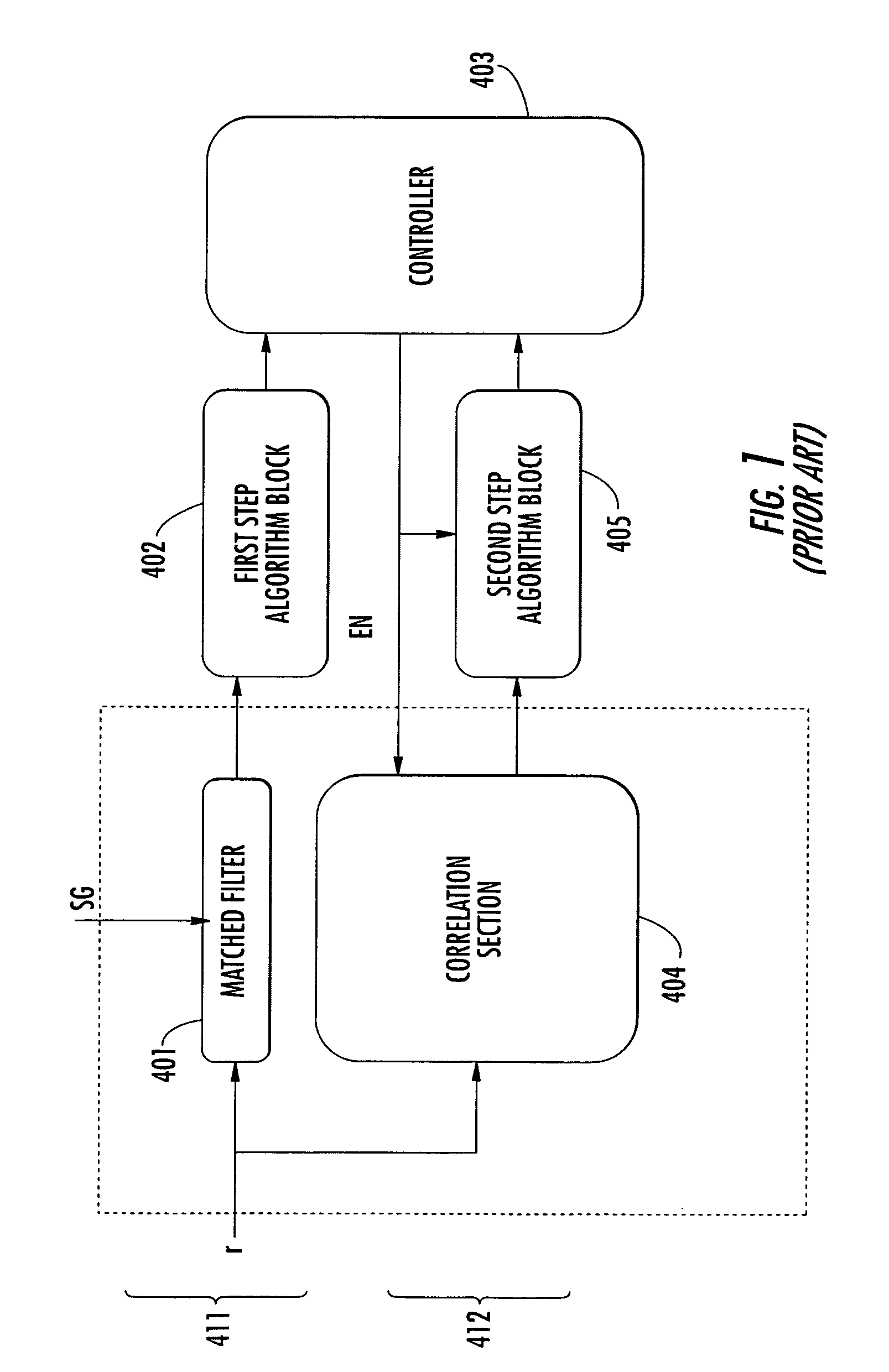
[0043]The first filter 210 and the second filter 220 together make up a matched filter, corresponding to the filter 401 of the primary channel P...

second embodiment

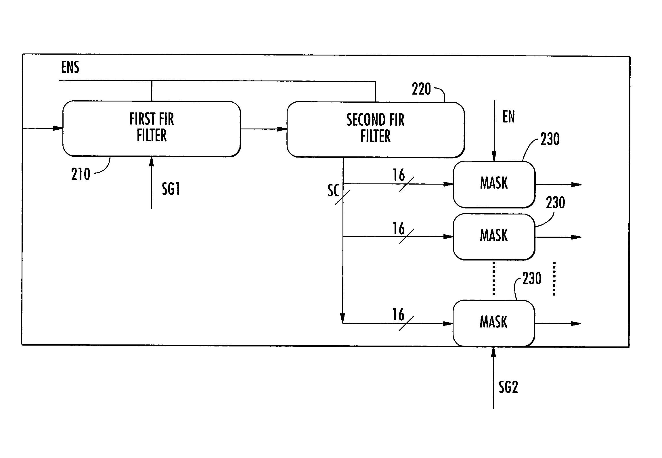
[0045]a serial architecture for implementing the correlation section in FDD mode is illustrated in FIG. 6. The received signal r is provided at the input to the first matched FIR filter 210, which also receives the first Golay sequence SG1 for the code SSC. The first filter 210 is followed by the second filter 220, both of which are driven by the enable and stop signal ENS.

[0046]The second filter 220 then supplies at its output the 16-bit correlation signal SC to a mask 231, which is designed for applying the weights corresponding to each secondary code SSC. The mask 231 receives the secondary code SSC to which the weight from an appropriate code generator 233 is to be applied. The code generator supplies the second 16-chip sequences for the secondary codes SSC and is driven in turn by a 16-value counter 232, which supplies the generator with the number SSCN of the secondary codes SSC to be correlated.

[0047]Both the counter 232 and the code generator 233 are also driven by an enabli...


PUM


Abstract

In a first step, slot synchronization may be obtained by setting in correlation the received signal with a primary sequence, which represents the primary channel, and storing the received signal. During a second step, the correlator may be re-used for correlating the received signal with a secondary sequence corresponding to the secondary synchronization codes. The correlator may include a first filter and a second filter connected in series, which receive a first secondary sequence and a second secondary sequence, which may include Golay sequences. Architectures of parallel and serial types, as well as architectures designed for reusing further circuit parts are also disclosed. The invention is particularly applicable in mobile communication systems based upon standards such as UMTS, CDMA2000, IS95, and WBCDMA.

Description

FIELD OF THE INVENTION[0001]The present invention relates to the field of telecommunications systems. More particularly, the present invention is particularly applicable to telecommunication systems based upon the Code-Division Multiple Access / Third-Generation Partnership Project Frequency Division Duplex (CDMA / 3GPP FDD), and the Code-Division Multiple Access / Third-Generation Partnership Project Time Division Duplex (CDMA / 3GPP TDD) standards, for example.[0002]The present invention will be described with reference to the above-noted applications for clarity of explanation. Even so, it will be understood that the present invention may be used for other applications as well. More particularly, the invention is applicable to various telecommunications systems in which operating conditions are similar to those described further below occur. By way of non-limiting example, such applications may include satellite telecommunication systems and mobile cellular systems corresponding to the U...

Claims


Application Information

Patent Timeline
IPC IPC(8): H04J15/00H04J3/06H04B1/707H04B7/00
CPCH04B1/70735H04B1/7083H04B1/709H04B2201/70707
Inventor RIMI, FRANCESCOAVELLONE, GIUSEPPEPAPPALARDO, FRANCESCOSPEZIALI, FILIPPOGALLUZZO, AGOSTINO
Owner MICROELECTRONIC INNOVATIONS LLC
Why Eureka
Try Eureka