Radiographic image processing method and apparatus

a radiographic and image processing technology, applied in the field of radiographic image processing methods and apparatuses, can solve the problems of difficult to apply x-rays upon specifying a phase in a respiratory cycle, radiography becomes complicated, and the difference method for chest still images cannot be simply applied to such operations, so as to improve diagnostic performance, shorten the diagnosis time, and achieve accurate difference images

Active Publication Date: 2008-06-10
CANON KK
View PDF14 Cites 22 Cited by
  • Summary
  • Abstract
  • Description
  • Claims
  • Application Information

AI Technical Summary

Benefits of technology

[0014]According to the radiographic image processing method and apparatus of the present invention, of the chest respiratory moving images radiographed along with respiration, a reference image at one time point which has a phase approximate to the respiration phase of a basic image at the other time point is determined, and difference processing between the two images is performed. This makes it possible to cancel out phase differences dependent on radiography and allow accurate difference processing, thus improving diagnostic performance.
[0015]In addition, if positioning of a basic image and reference image is performed before difference processing, a more accurate difference image can be obtained, and the diagnosis time can be shortened.

Problems solved by technology

In contrast to this, when chest moving images are to be obtained by radiography along with respiration, it is difficult to apply X-rays upon specifying a phase in a respiratory cycle.
In this case, however, a tool must be attached to the patient, and radiography becomes complicated.
Therefore, the difference method for chest still images cannot be simply applied to such operation.

Method used


Image

  • Radiographic image processing method and apparatus
  • Radiographic image processing method and apparatus
  • Radiographic image processing method and apparatus

Examples


Embodiment Construction

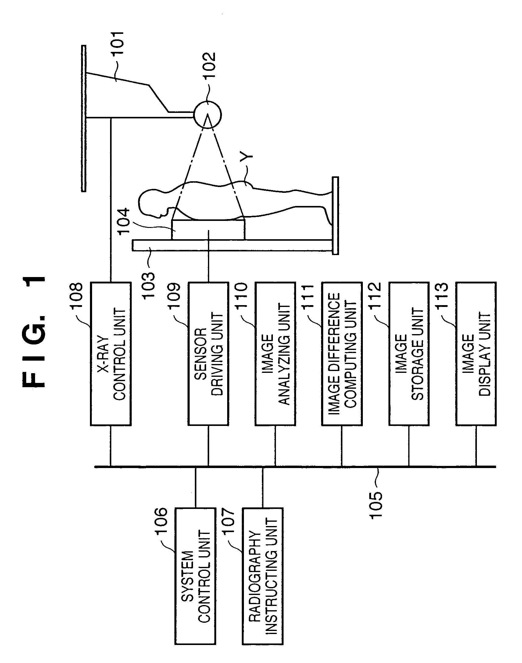
[0032]FIG. 1 is a view showing the arrangement of an X-ray imaging apparatus, in which a two-dimensional X-ray sensor 104 fixed to a stand 103 is placed in front of an X-ray tube 102 suspended from the ceiling through a ceiling suspended portion 101, and an object Y to be examined is positioned on the X-ray tube 102 side of the X-ray sensor 104.

[0033]A system control unit 106, radiography instructing unit 107, X-ray control unit 108, sensor driving unit 109, image analyzing unit 110, image difference computing unit 111, image storage unit 112, and image display unit 113 are connected to each other through a system bus 105. The system control unit 106 controls the timing of driving each constituent element and the flow of data. The system control unit 106 can be constructed from computer programs. The output of the X-ray control unit 108 is connected to the X-ray tube 102. The output of the sensor driving unit 109 is connected to the X-ray sensor 104. The sensor driving unit 109 can ...


PUM


Abstract

N images in a respiratory cycle which are radiographed in year P are input, and binary lung field images are extracted from the respective front chest images. Lung field areas S and lung field heights are then calculated. In forming area and height variation waveforms, regions of the N input images are obtained and plotted. Each image is determined as an image belonging to the inspiration mode or expiration mode. The respective images are sorted and stored. Similar processing is performed for N images in a respiratory cycle which are radiographed in year P+1, and the resultant images are stored. Difference images are obtained from the basic images radiographed in year P+1 and the reference images radiographed in year P for each mode by image analysis, thereby extracting changes over time.

Description

FIELD OF THE INVENTION[0001]The present invention relates to a radiographic image processing method and apparatus which extract changes over time by analyzing a plurality of sets of respiratory moving images which are radiographed along with respiration at different time points and performing difference processing.BACKGROUND OF THE INVENTION[0002]Recently, there has been developed a system which takes radiographic images of an object by using a large-area semiconductor image sensor. This system has the practical merit of being capable of recording images over an extremely wide radiation exposure range as compared with a conventional radiographic image system which uses silver halide radiography.[0003]That is, the semiconductor image sensor reads X-rays in an extremely wide dynamic range as electrical signals by using a photoelectric conversion means, and converts the electrical signals into digital signals. These digital signals are processed to output radiographic images as visible...

Claims


Application Information

Patent Timeline
Patent Type & Authority Patents(United States)
IPC IPC(8): G06K9/00G01T1/00A61B6/00G03B42/02G06T1/00G06T7/20
CPCG06T7/2053G06T7/254
Inventor TAGO, AKIRATSUJII, OSAMU
Owner CANON KK
Why Eureka
Try Eureka